Introduction
My RAM expansion for the Amiga 600 broke 🙁 Instead of getting an old and used one I decided to have a look if there are any affordable new expensions out there.
Unfortunatly, the cheap expensions got no RTC, that seems to be a feature of the expensive cards. Well OK, I’ll make my own then.
The gerber files at the end are licensed with the CC BY-NC 3.0-License.
To make it short: No commercial use, you’re free to use them personally and keep my name on it 🙂
Gathering information
I used my broken expansion as a start. To have a look at all the traces and connections I pulled off all the components. The card was wonky anyway – it some corrosion by a leaking battery and wasn’t recognized by the Amiga all the time.
 It’s pretty simple – the RAM ICs are connected to the Amiga’s RAM-Bus. The RTC gets its clock signal by an external oszillator. To keep its time it relies on a battery backup when the Amiga is switched off.
The card also features a circuit to charge a battery – but I won’t be using that. I’ll instead use a non leaking battery.
Planning
So, let’s have a look at the Amiga’s expansion port:
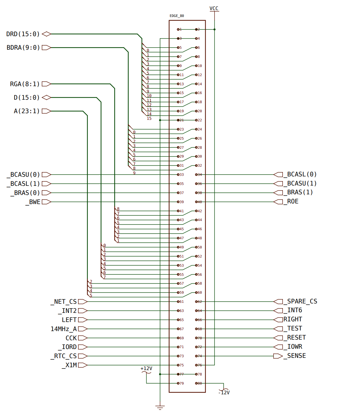
It’s pretty self-explanatory: the DRD(ate) and BDRA(dress)-Lines of the RAM-Bus are present. Just wire the new RAM ICs to it. . The Amiga has two 256Kx16-ICs built in, I’ll use them for my expansion as well. They’re pretty cheap, costing about $2 each.
The next thing is the RTC circuit.
I traced the old RTC-IC (MSM6242B) and had a look at the datasheet for it:
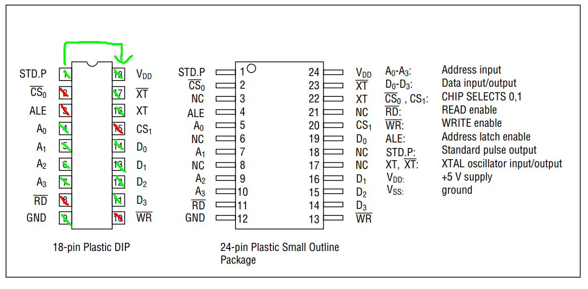
Green – I already know what to do with these pins
Red – connected to the expansion port, I’ll have see how to route them
And hey, there seems to be a nice PSOP-package available. I’ll use that for my expansion.
When searching for clock circuits I stumbled upon this circuit, it couldn’t get any easier than that:
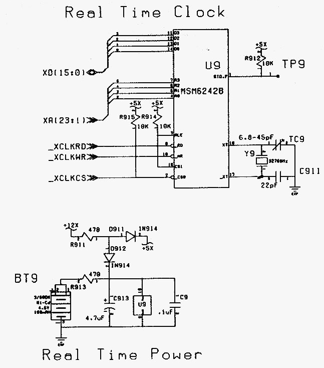 Wiring the clock IC was pretty easy now, but i reworked the power section. The circuit diagram above features a charging circuit for a battery, I won’t be using that. I’ll be using a 3V coin cell battery instead. The IC keeps it’s time while powered at 2V, so a battery should be more than sufficient.
A double schottky diode (BAT54C) manages the switching between the Atari’s and the batterie’s power. To ensure the switching works without any power outages a low ESR capacitor by Philips is connected to the battery.
And this is how my circuit looks like:
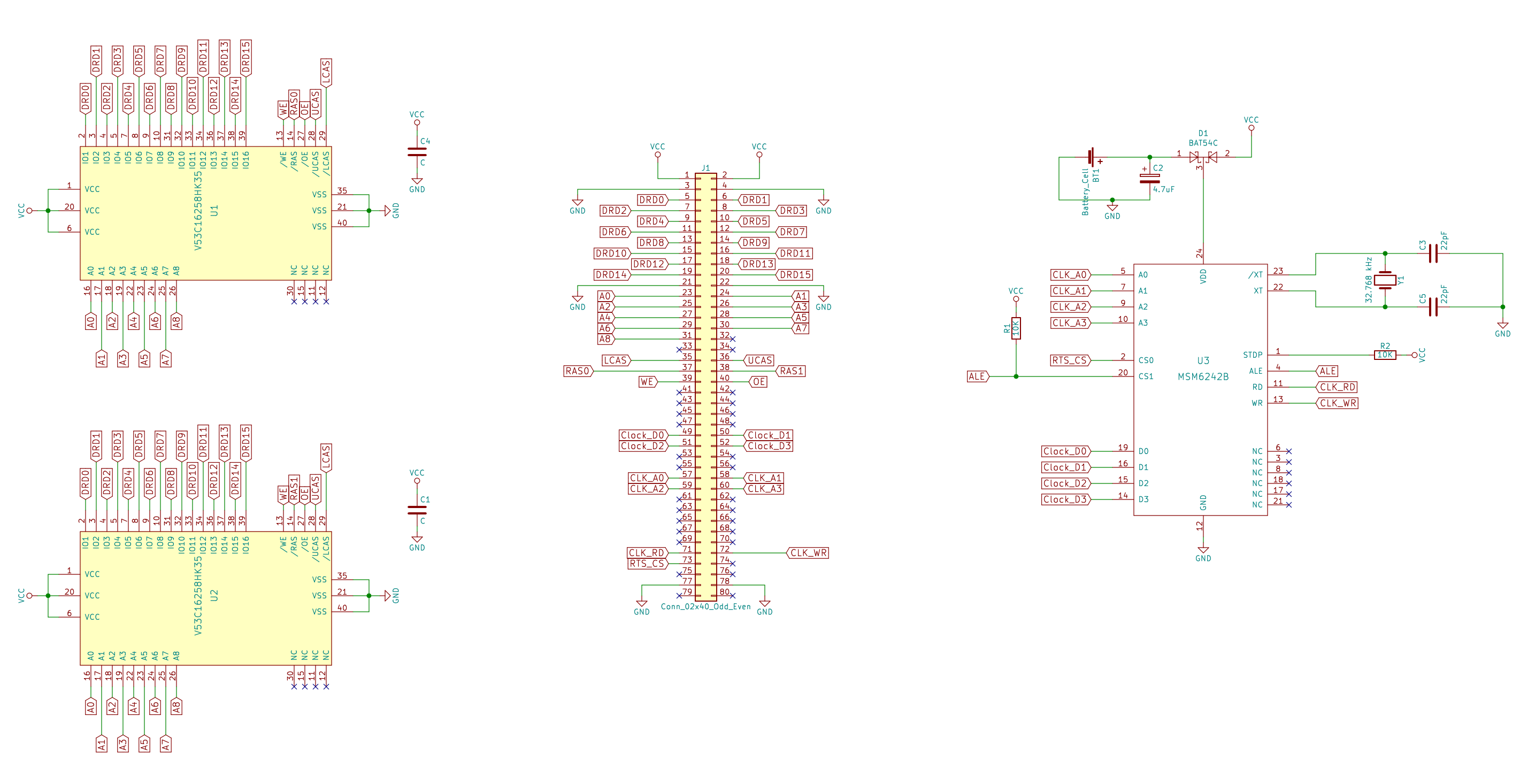 Don’t worry, a vector diagram of this circuit is attached at the bottom of this post 🙂
Layout planning and gathering components
To save space I focused on smd parts.
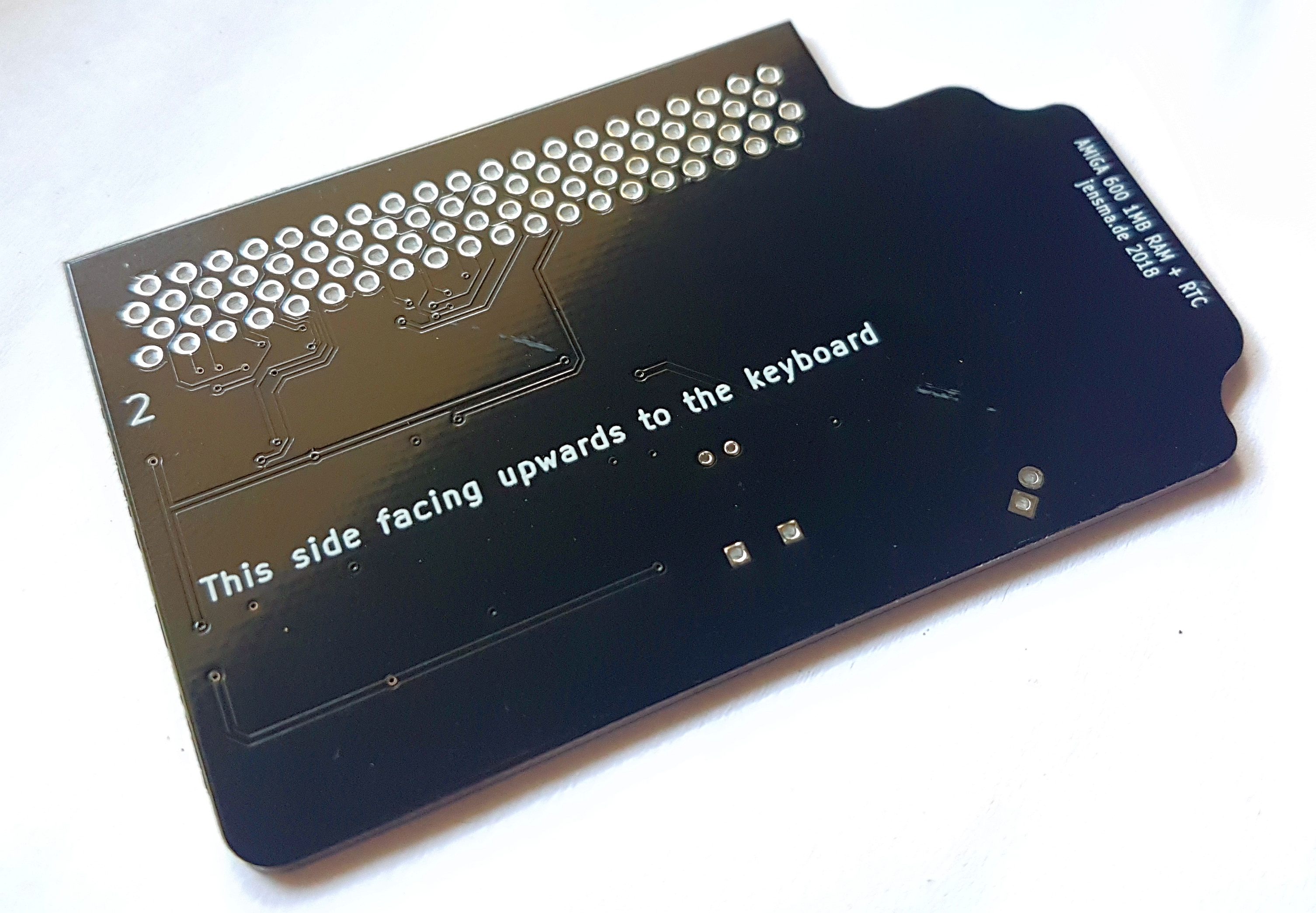
The search for a socket connector was harder than expected. Ultimatively my only choice was the Adafruit 3342. Its angled and puts the connectors in four rows on the pcbs. Not quity nice, but do-able. The angle used a lot of space so I had to plan the whole pcb upside down – no worries, you’ll see what I mean in the end 🙂
For the RAM I chose the same type that was already on the Amiga. The cheapest I could find was in a SOJ-package. Brr, I don’t like these, but hey, they’re cheap.
The battery is held down by an smd battery holder for a common CR2032. That way it’s easily changeable.
I got all the components from mouser except the RAM and the RTC IC which I got from aliexpress.com respectively.
PCB manufacturing and assembly
This is how the finished pcb looks like, with indentation for an easier removal from the expansion port:
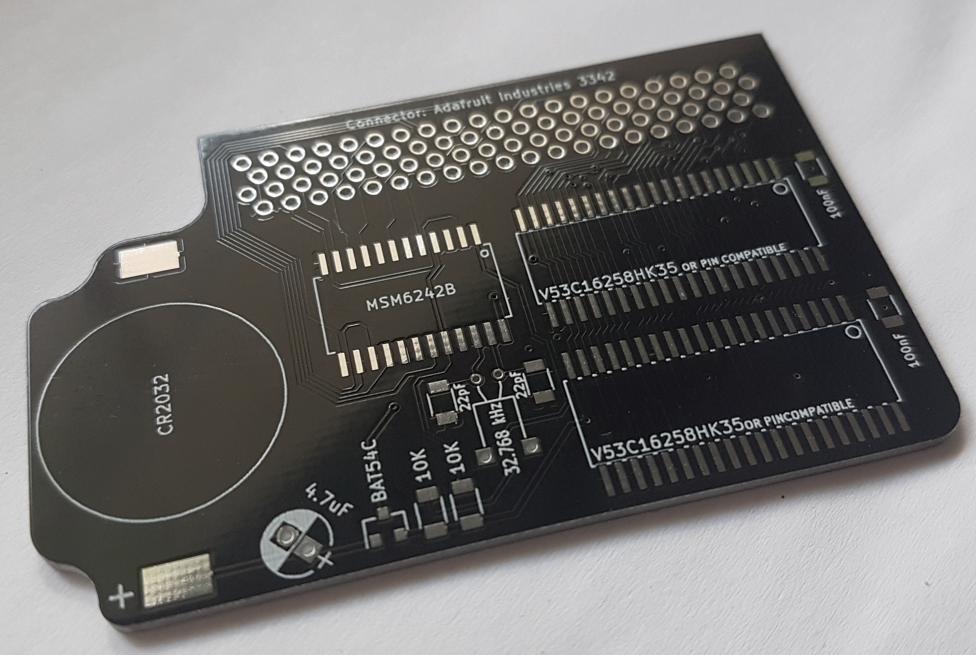 I like to mark every component’s on the pcb, that should make repairs easier 🙂
 This is how the pcb looks assembled:
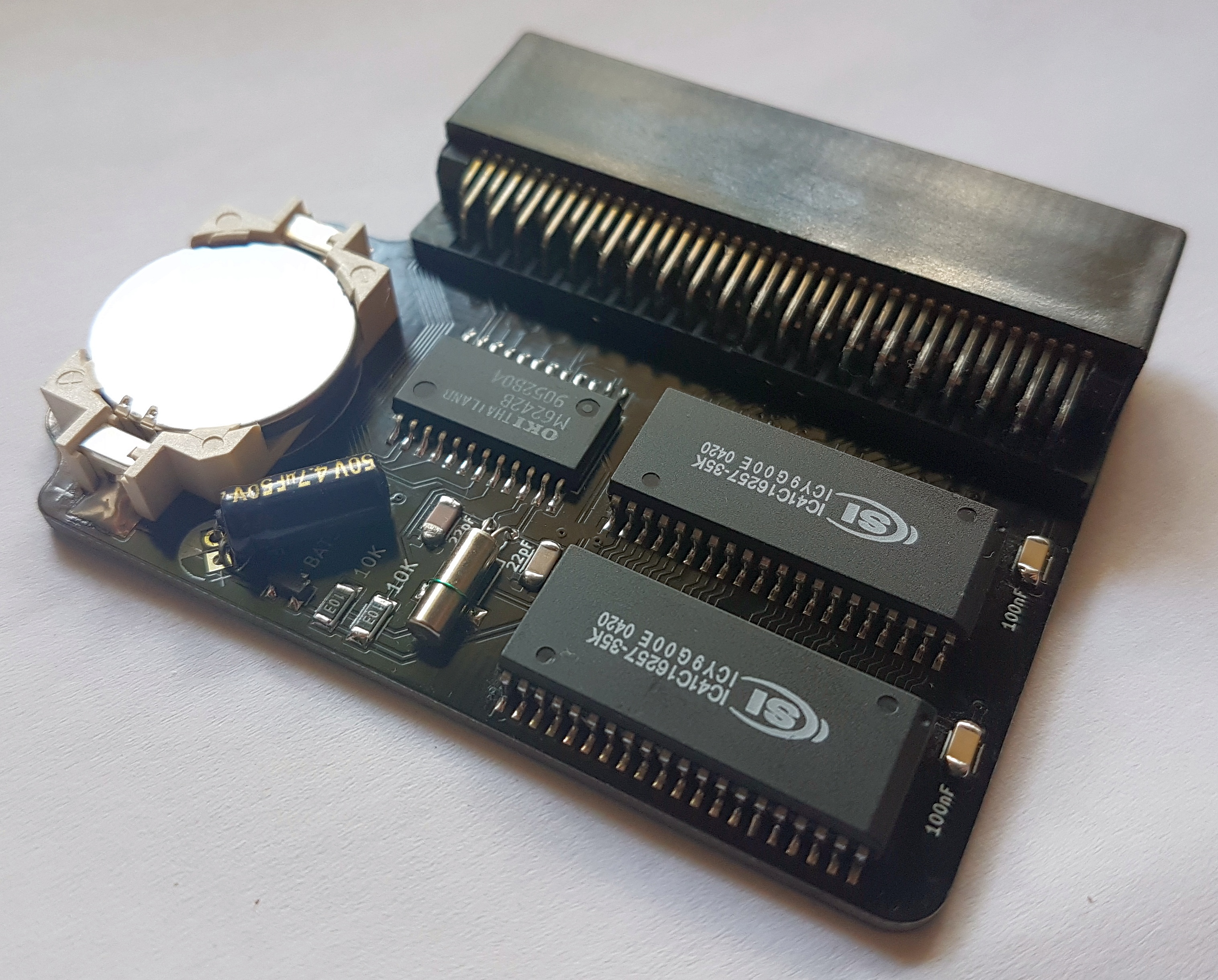 I started to solder down the smallest parts first and the connector at the very last. I strapped down the quartz crystal with some wire so it’s not flapping around in the breeze 🙂
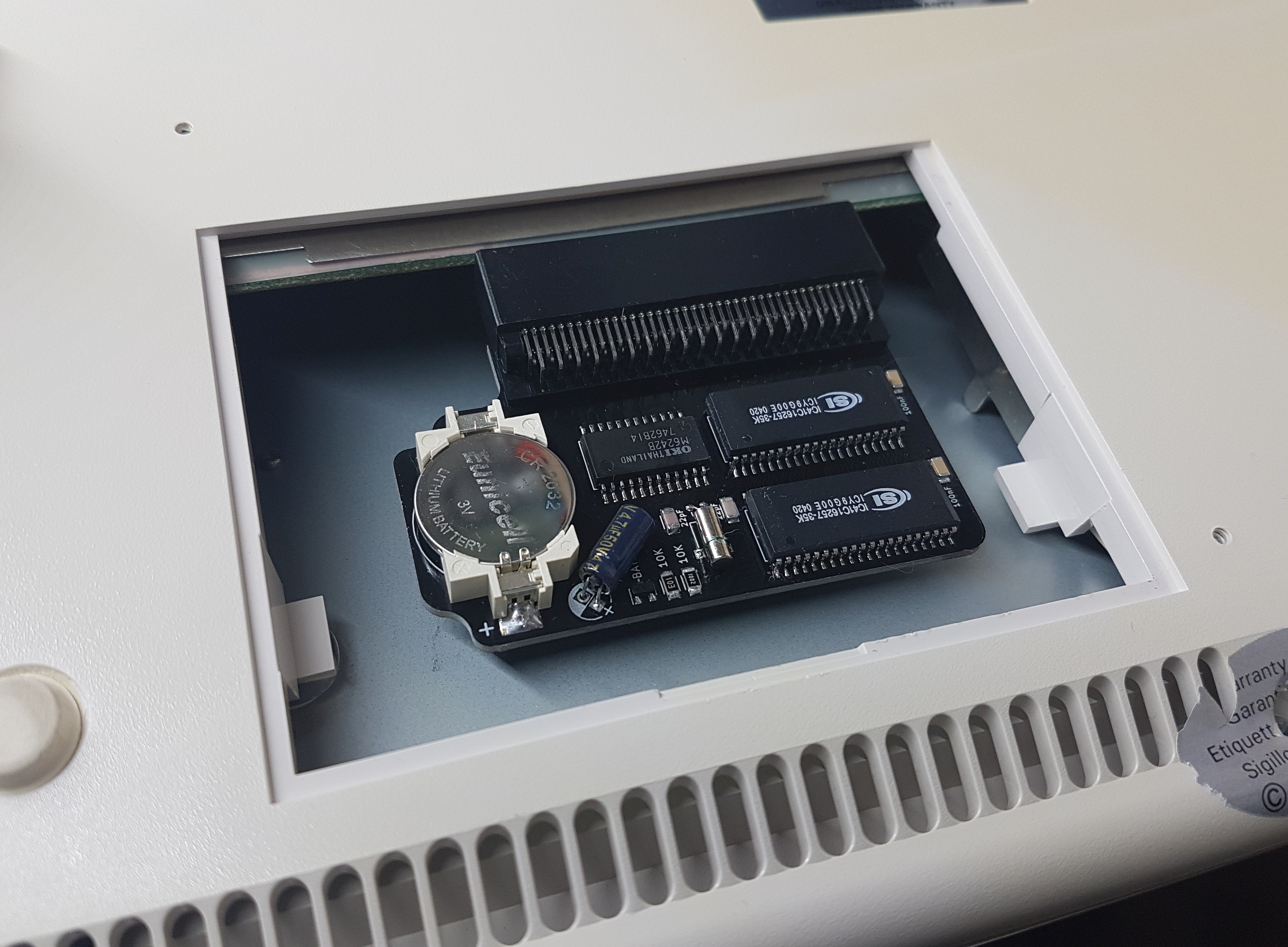
The battery should last over 3 years, considering the loss through the capacitor and the RTC IC’s power usage for keeping the time. This is how the epxansion is mounted inside the Amiga:
Epilogue
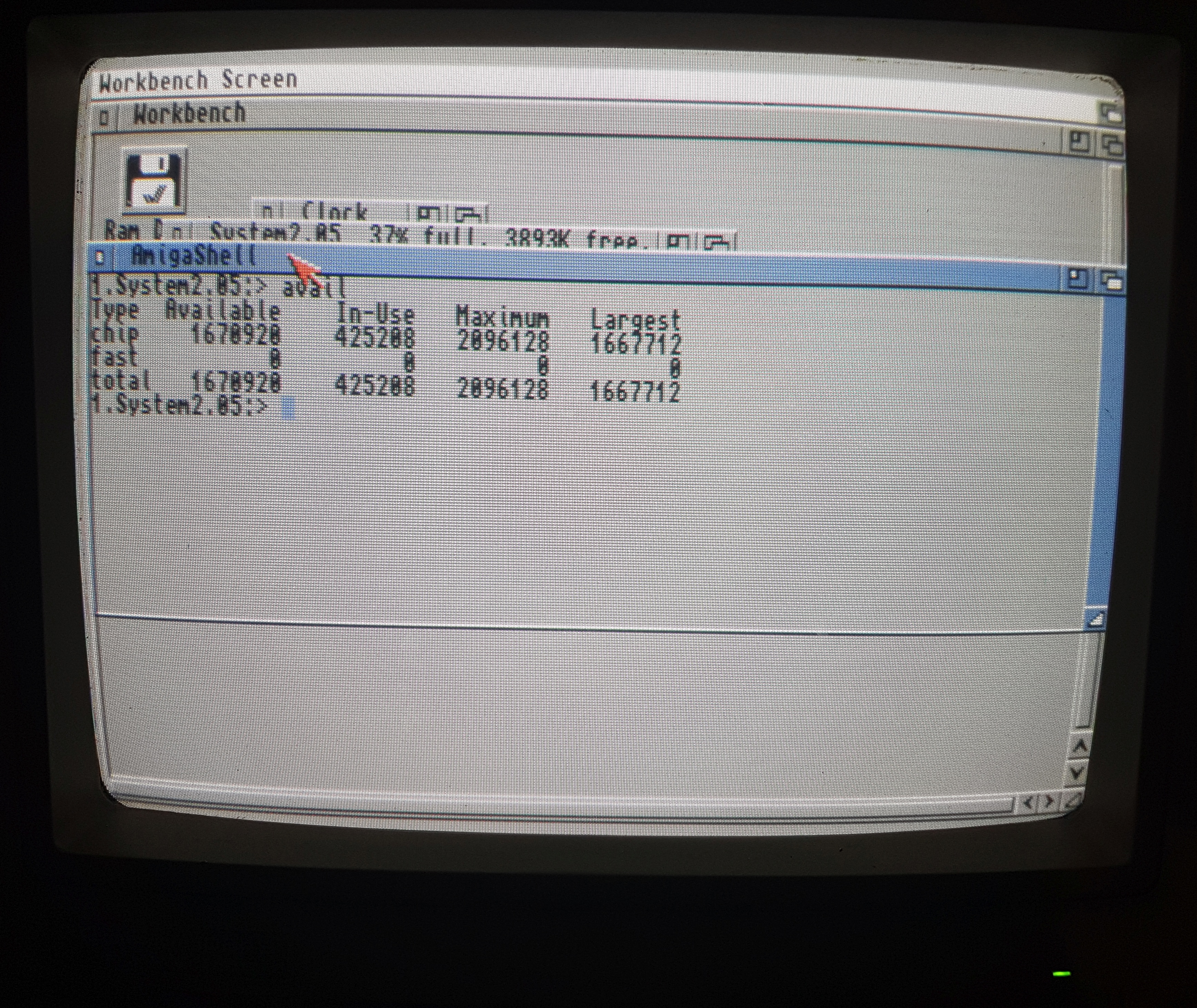
To test the RAM you simply open up a shell and type “avail“. Have a look at the “maximum” column, it should say 2096128 bytes:
 You can set the Amiga’s time with the “date“-command. For example: “date 01-Nov-98 14:10“. After setting the time you have to store it in the expansion card’s RTC IC with: “setclock save”
PS: I have some components for this pcb for sale, just drop me a note.
Download
Download circuit + gerbers
Or get the pcb directly from oshpark: https://oshpark.com/shared_projects/G0D5QyWy