https://github.com/jensma-de/ditherwiz – A web-based dithering program. It supports various algorithms and color palettes. I was playing an old PC-98 game and wanted to create images using a similar dithering technique.
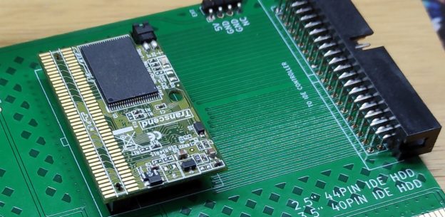
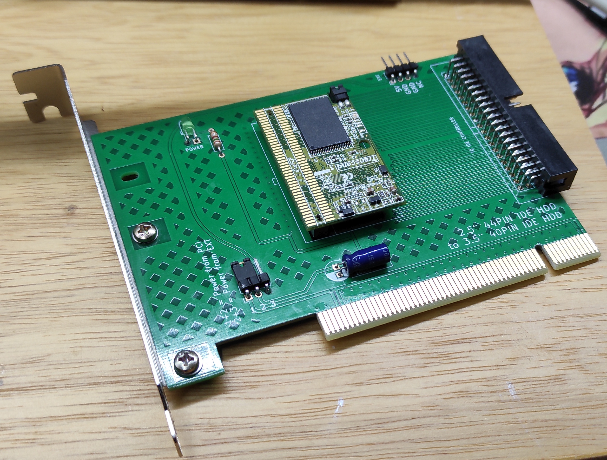
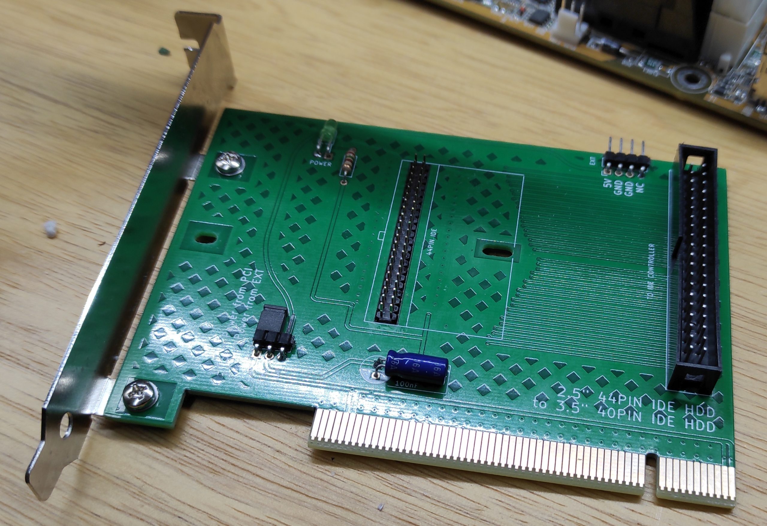
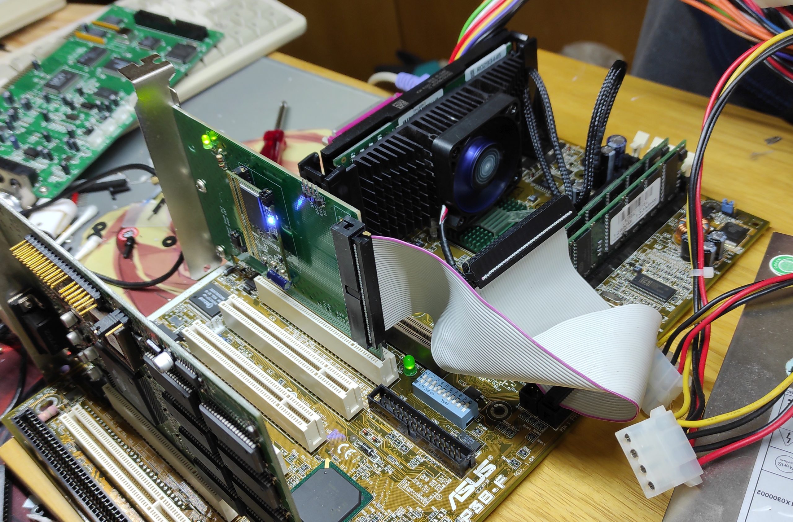
Just another quick one: I wanted to use a small flash IDE in a desktop PCI. Unfortunatly those devices really aren’t meant to be mounted in an ATX case, so I wound up a small adapter. The power for the flash HDD comes either from the PCI port or an external source. Kicad project files and gerbers are attached, in case you want to replicate this project 🙂
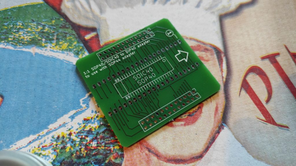
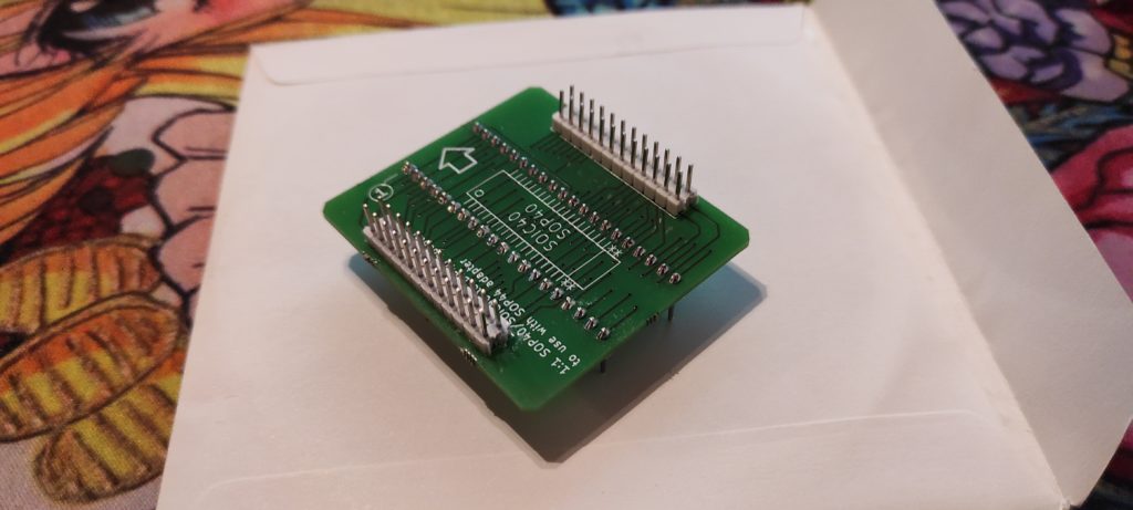
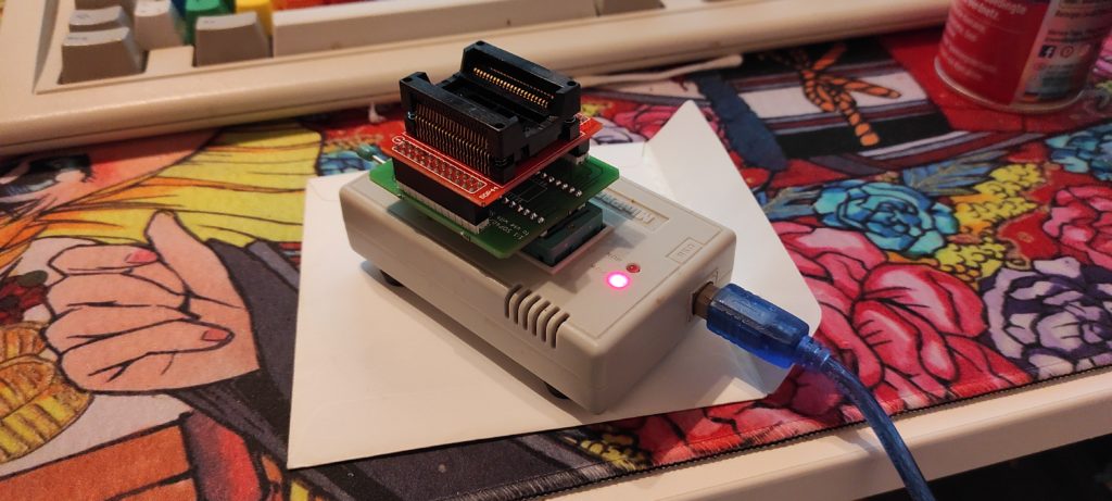
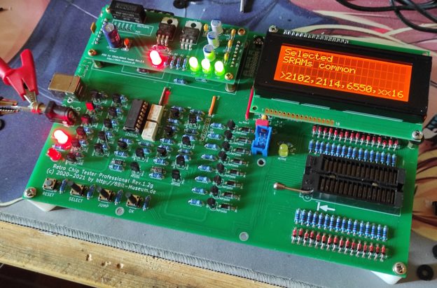
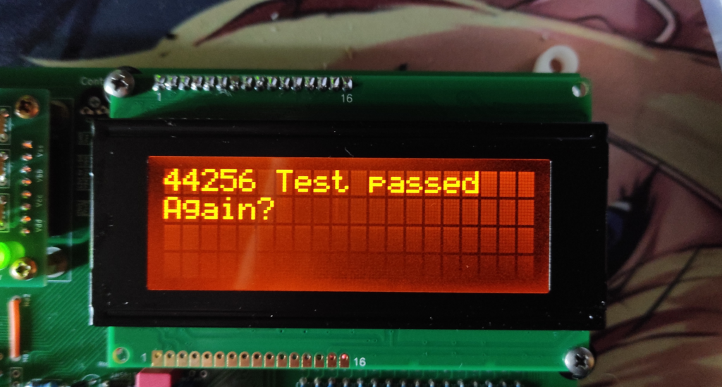
Just a quick note: If you’re testing old chips regularly you might want to have a look at the Retro Chip Tester Professional!
(This article isn’t sponsored, I’m just amazed by this device 🙂 )
PS: The first test was successful, woohoo!
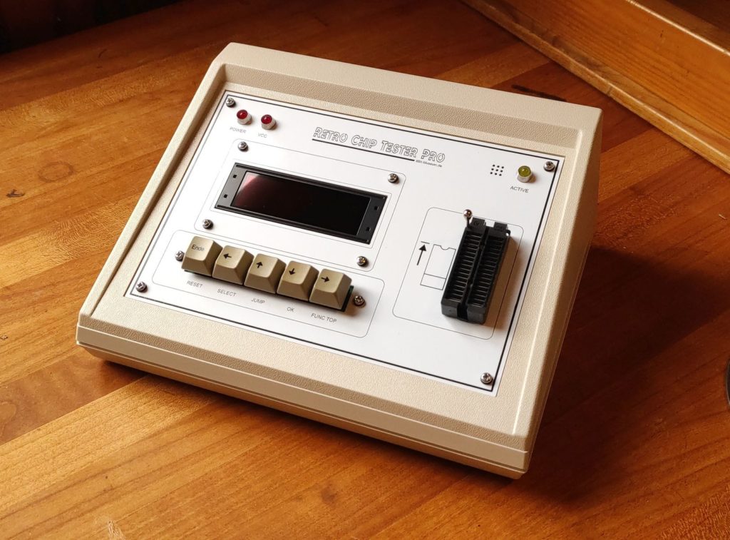
Housing
I put the RCT in a fancy housing:
You can get the housing at Mouser. But you have to customize it yourself 🙂
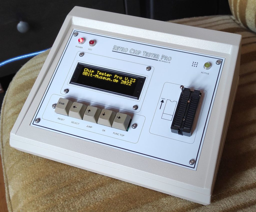
I also replaced the LCD with an OLED.
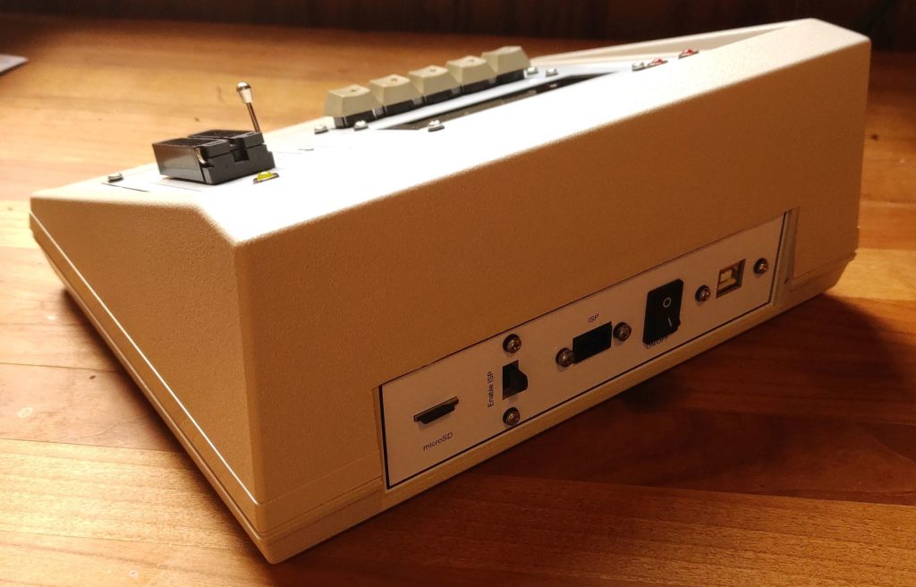
The ports and switches on the backside are mounted with several adapters und pcbs:
The SD card pcb was glued in place with a 3D printed block underneath to support it. That’s a bit unfortunate, but the pcb itself has no mounting holes.
I programmed a little game just for fun for my mini pc 🙂
It is a cute little puzzle game with the “Lights Out“-mechanic. The game needs about 1MB of RAM and a VESA2-capable video card. It attemps to auto config a sound card for 16bit sound and MIDI music. It is written in C++ and was compiled with djgpp.
Furthermore I designed it to fit on a single 3.5″-diskette because why not 😛
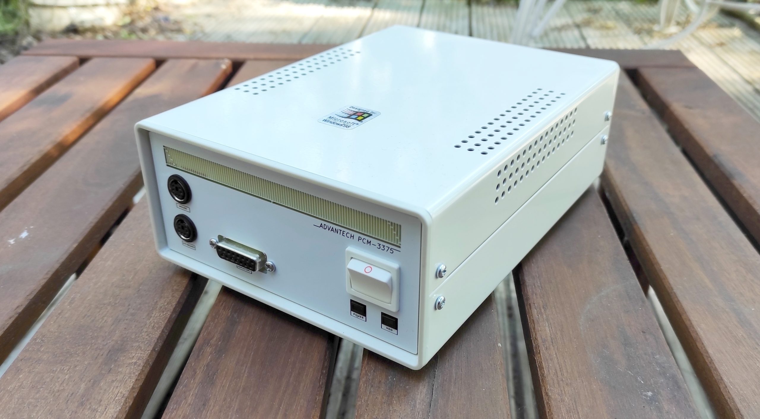
I saw TheRasteri’s video about a mini PC the other day and fell in love with the idea – so I built my own 🙂
The video in question:
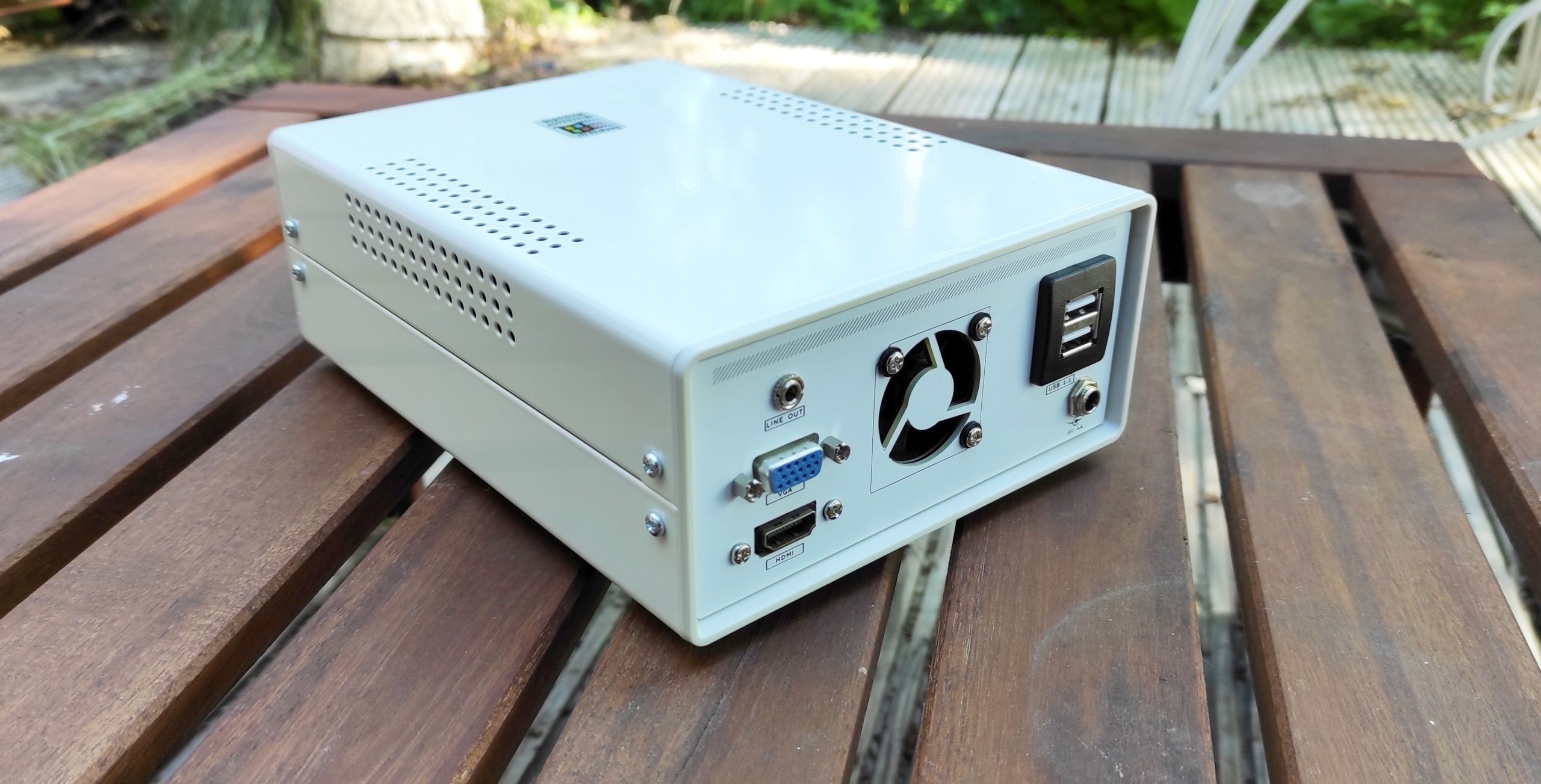
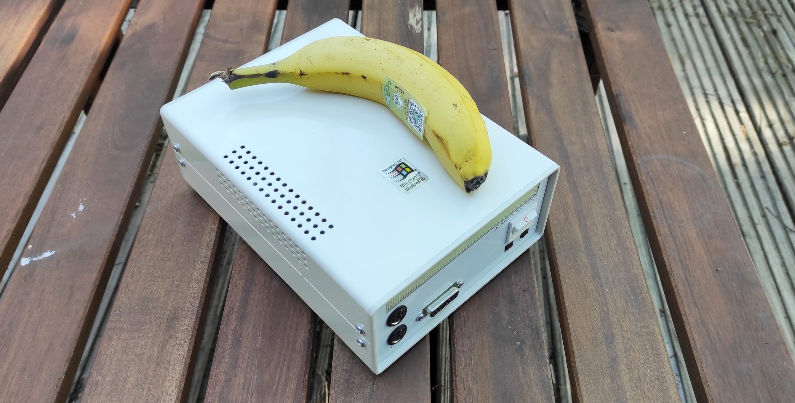
And that’s my take on the idea:
Curvy yellow fruit for scale
I got a somewhat good deal on a mainboard from the UK, took some measurements and build a face- and backplate for the casing. The clunky power switch and overall design tries very hard to look like a retro PC, haha 😀
Specs: CPU: Embedded low-power onboard VIA Mark 533 MHz RAM: 133 Mhz SDRAM 144-pin SODIMM 256MB HDD: 2GB CF-Card I/O: 2 x USB 1.1; 1x Gameport; 1x Line Out; 1x HDMI out; 2x PS/2; 1x VGA GPU: VIA Mark CoreFusion VRAM 32 MB Sound: *wink* *wink* Avance Logic ALS100 Plus+ PnP OPL3 sound card for PC/104 Power: 5V@4A
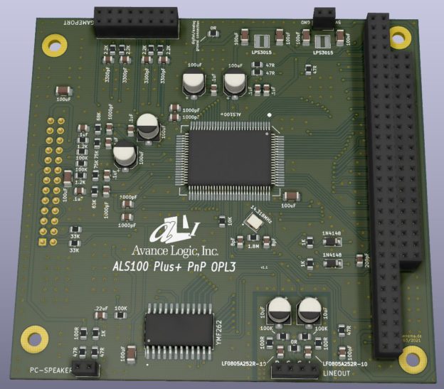
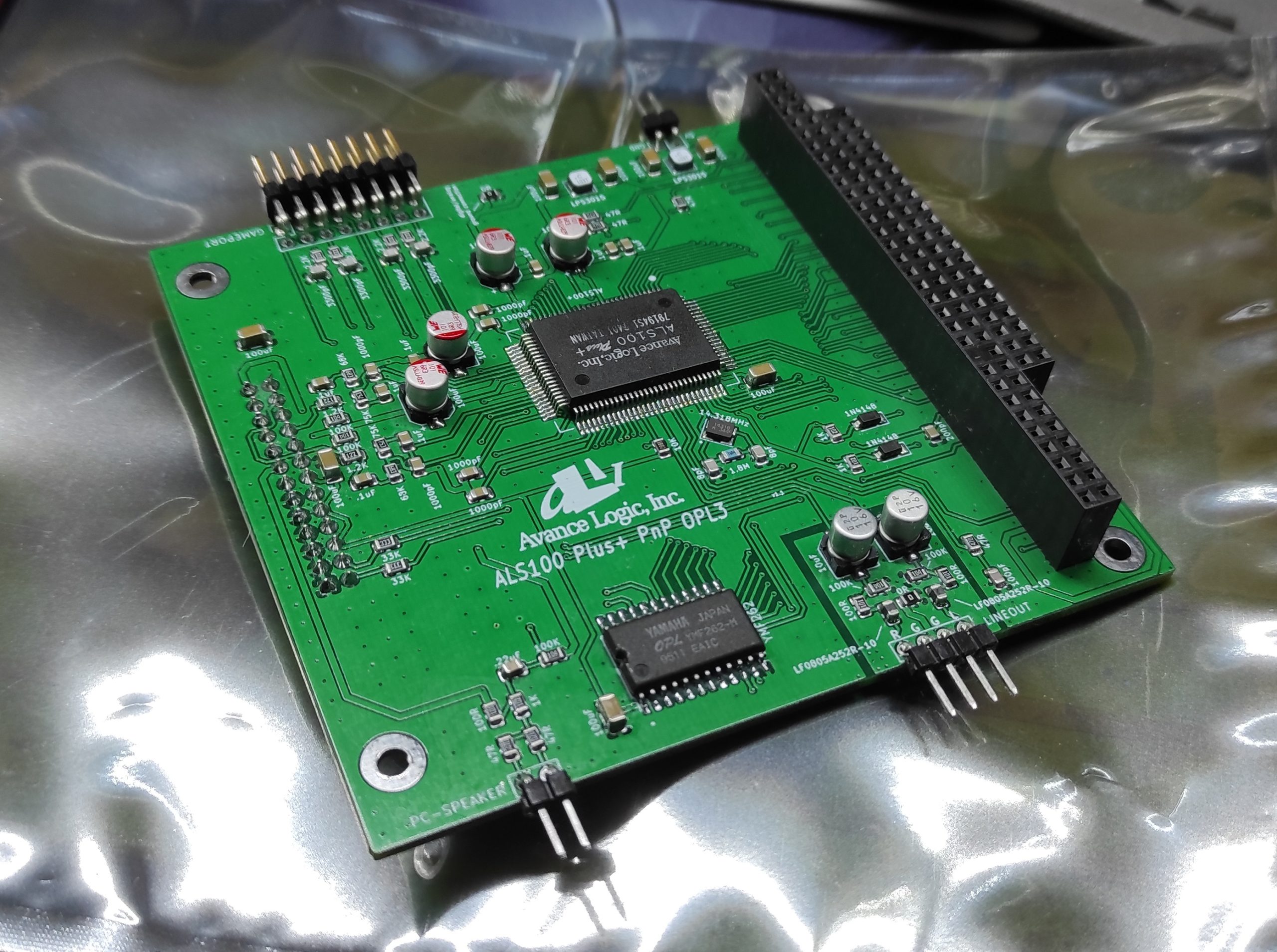
I’m currently building a tiny DOS gaming PC and needed a sound card for it. Unfortunatly there aren’t many PC/104* sound cards available so I spun up my own.
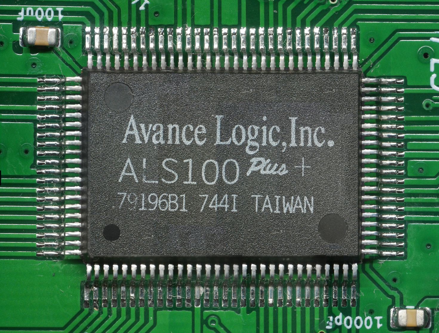
Since I wanted a sound card that was compatible with most standards so I can play as many games as possible with it I desided on the Avance Logic ALS100 Plus+. The IC is pretty well documented what made designing the sound card much easier.
It’s features are:
Compatibility • Adlib • All Sound Blaster Pro applications • All Sound Blaster 16 applications • MPU-401 UART MIDI • PC Speaker • Sound Blaster ADPCM • Yamaha OPL3 FM Synthesizer
That’ll cover every game I’m interested in. The PC speaker is mixed in with the audio out by the IC, that’s pretty cool.
The hardware specifications of the new sound card are as following:
Hardware specifications • Software selectable DMA lines (0, 1, 3) • Software selectable interrupt lines (5, 7, 9, 10, 11) • PC/104 ISA Plug and Play bus interface • DMA interface with FIFO • Enhanced Game port • 8-bit or 16-bit stereo digital audio from 4 kHz to 48 kHz • 3D Sound Effect Processor • FM/wavetable synthesis via OPL3 • Wavetable connector • Stereo Line-Out
Design and development
If you’re just here for the design files and aren’t interested in the failures I’ve had designing the sound card just skip to the end 🙂
Then I read the manufacturer’s design sheet to build a sound card for the ALS100 Plus+ and added some minor noise cancellation.
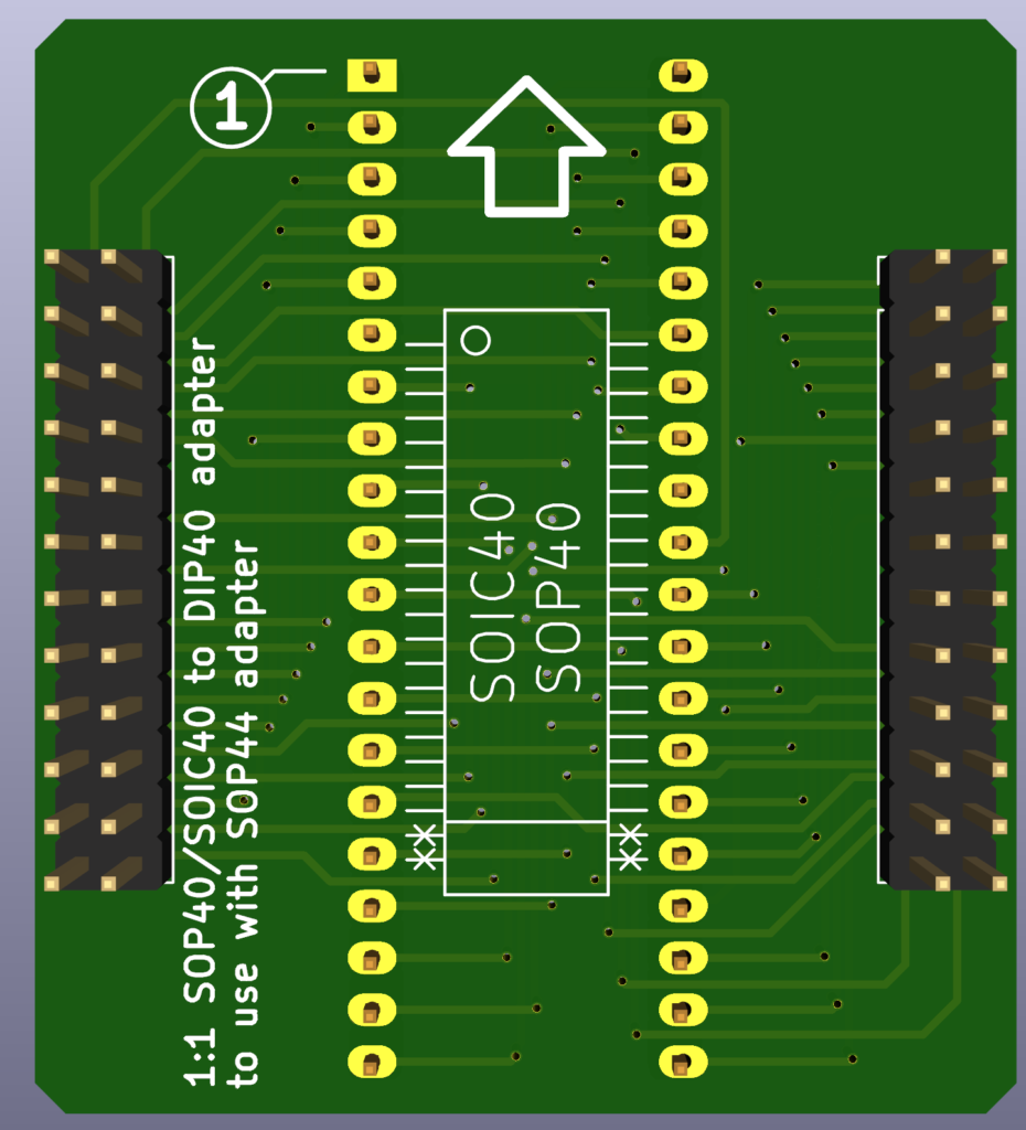
First fail:
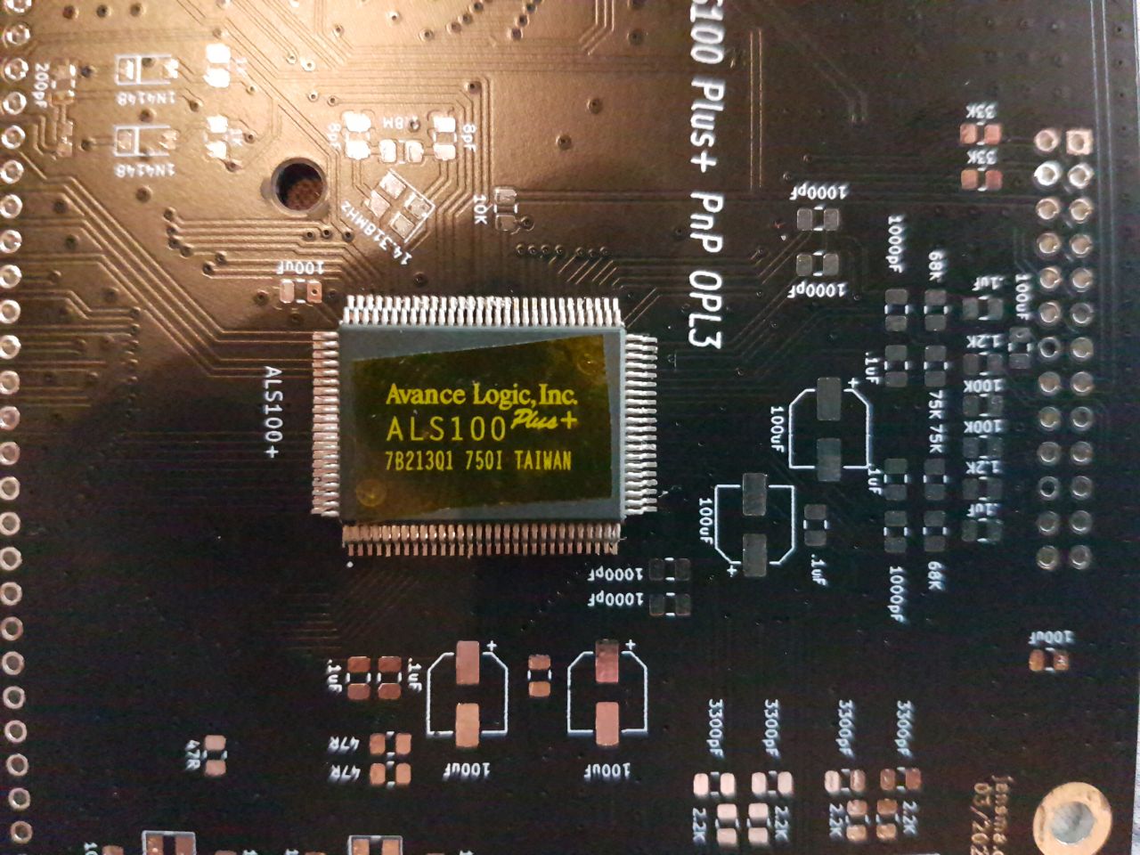
Yeah well, the IC is a bit bigger than a PQFP-100 (10% bigger to be exact). Meh. I tried to shorten the legs but ultimatively ordered another PCB. Bummer.
Second fail:
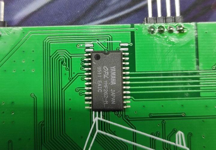
If you thought I would learn from my first mistake – think again! Yeah, so the OPL3 is also wider than a normal SOIC-24. This time I shortened the legs and soldered it down and went to testing (I shifted the IC down in the photo to better visualize the difference).
Third fail:
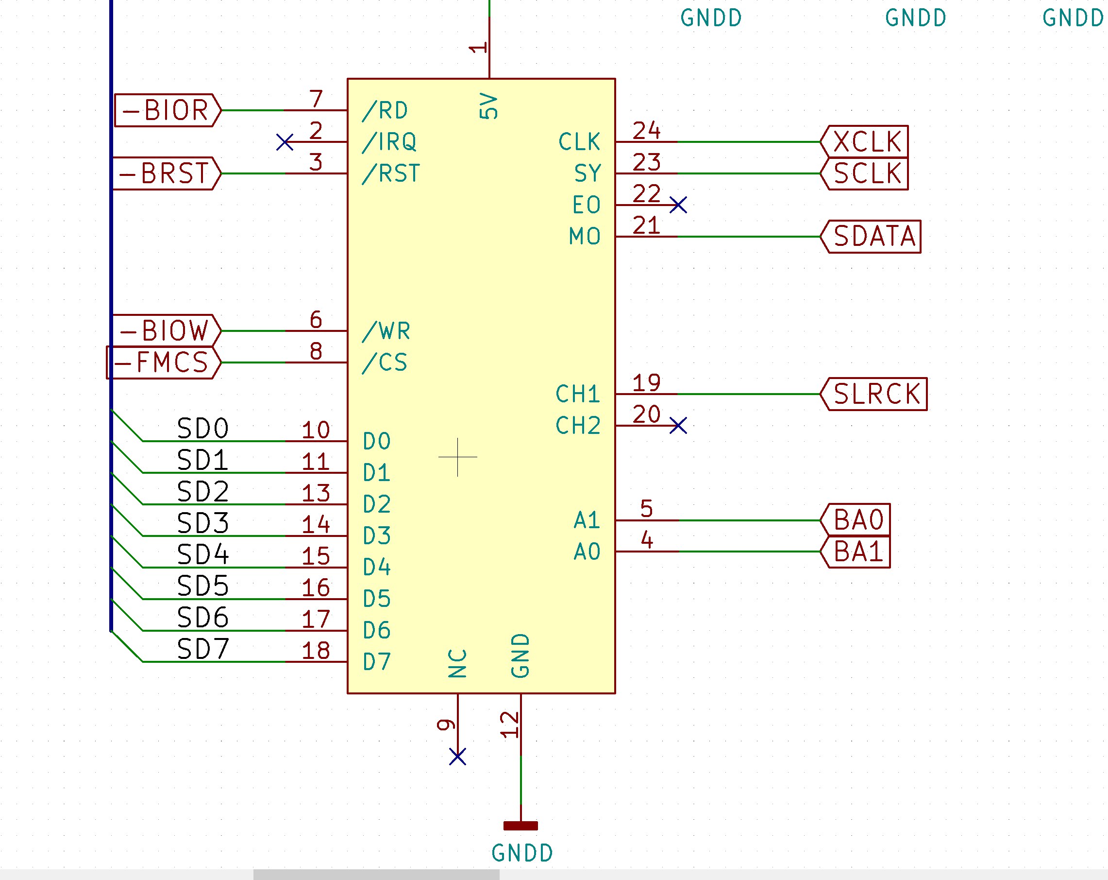
8bit- and 16bit-audio worked straight of the box so was the PC Speaker, but the FM synthesis was garbled. Staring at the schematics revealed another pretty stupid mistake:
If you havn’t spotted it yet: I switched around the adress lines. I cut the traces on the pcb and rewired them and FM synthesis was finally working.
Fourth fail (more like a foreseen issue):
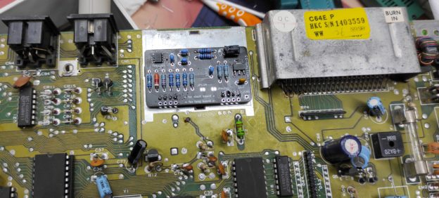
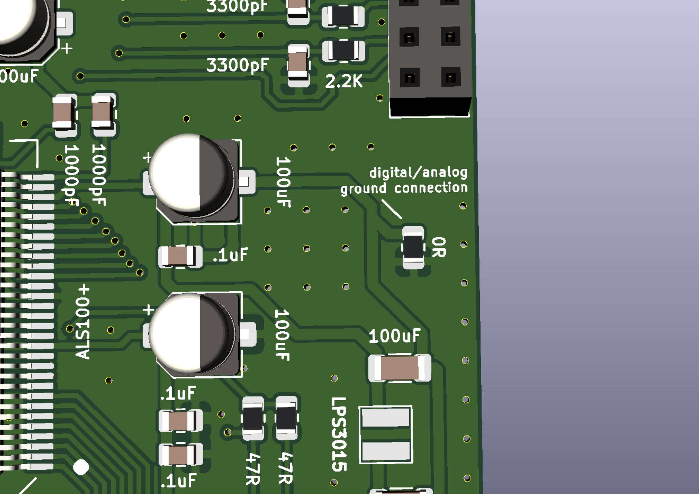
There was a faint hum in the audio when plugging in a wavetable daughterboard. The soundcard has a digital and an analog ground which are connected at one point:
That’s fine and dandy – but the wavetable did just the same, so it created a ground loop. I removed the resistor on the sound card and the hum was gone 🙂
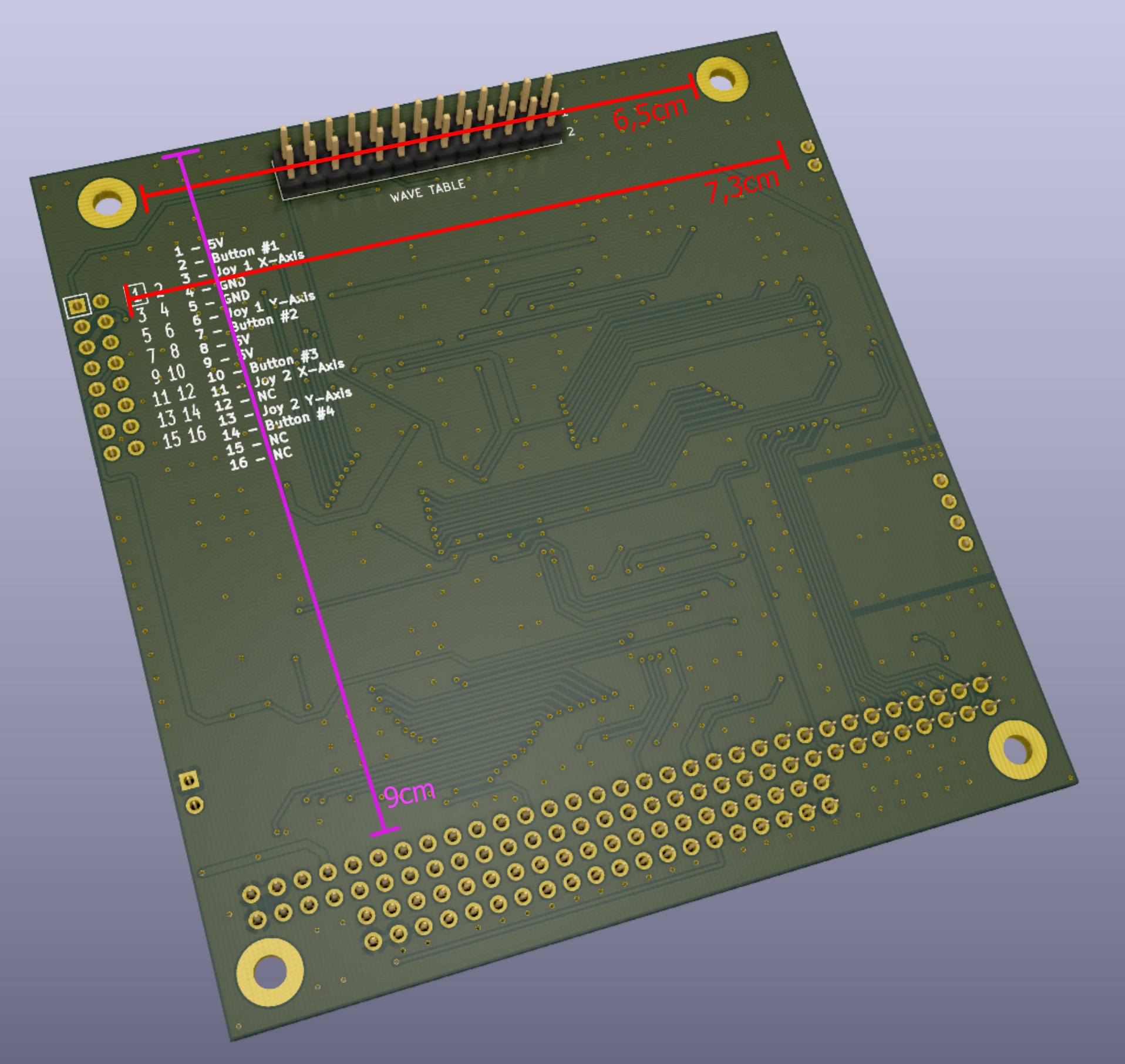
The dimensions for the wavetable daughterboard are approximately like this:
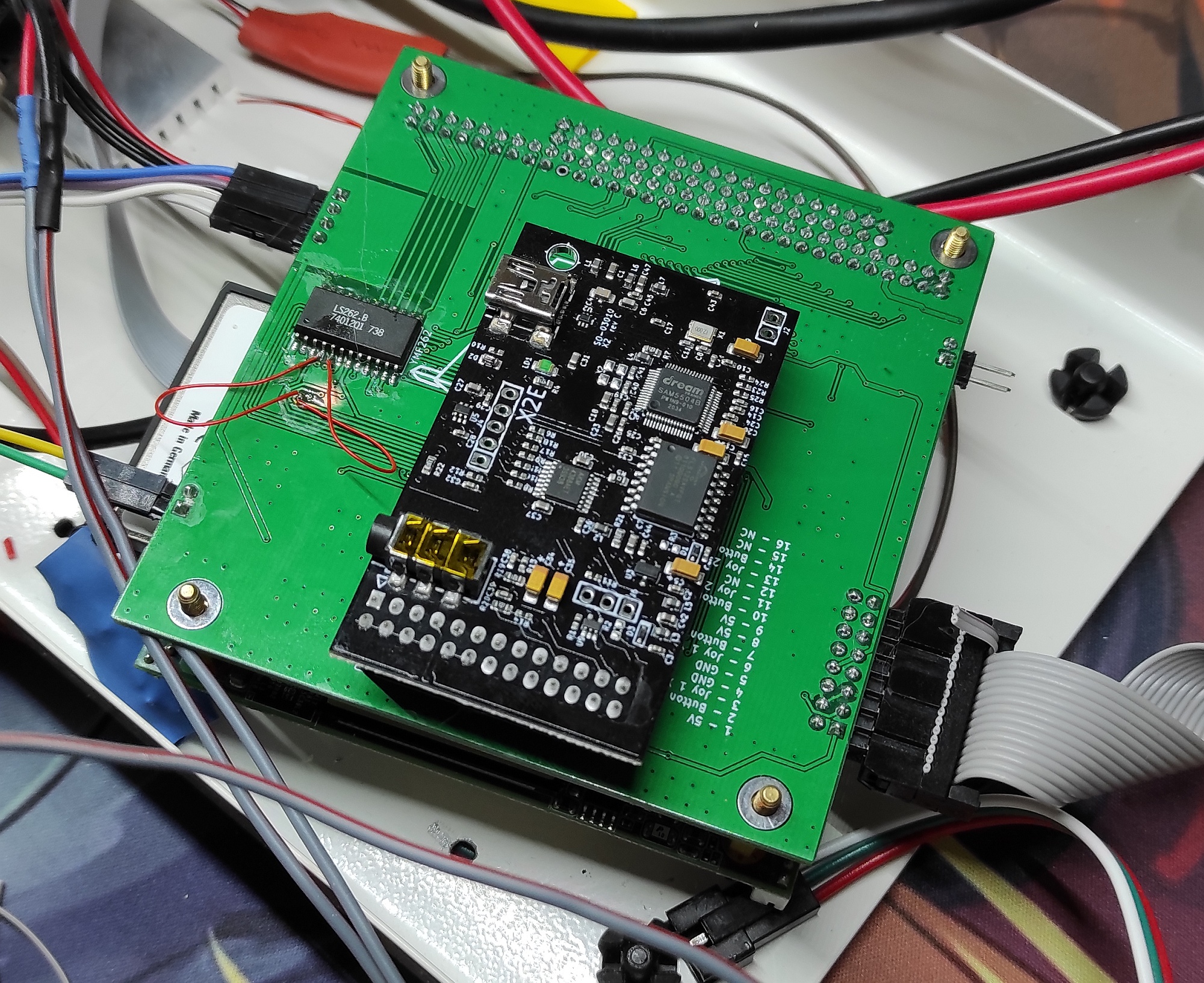
While testing I used a Dreamblaster X2 which fits nicely. Also pictured: The fix for fail #1 and an OPL3-clone.
*= Missing from BOM: • PC104-Connector, available on mouser.com • OPL3, available new old stock from various suppliers • ALS100 Plus+, unfortunatly EOL since the late 90s, so you have to desolder it from a working sound card.