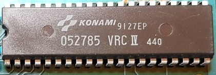
Since the most questions people send me are about VRC4 repros I think its handy to have a dedicated post for some infos about them 🙂
If you want to convert a VRC4 game into another you need to rewire the VRC4 in some cases. Have a look at this chart:
Any VRC4 to VRC4b
Lift pin 3 of VRC4 (skip if coming from a VRC4a)
Lift pin 4 of VRC4
Solder pin 3 of VRC4 to PRG pin 11 (skip if coming from a VRC4a)
Solder pin 4 of VRC4 to PRG pin 12
Any VRC4 to VRC4c
Lift pin 3 of VRC4
Lift pin 4 of VRC4
Solder pin 3 of VRC4 to PRG pin 6
Solder pin 4 of VRC4 to PRG pin 5
Any VRC4 to VRC4d
Lift pin 3 of VRC4
Lift pin 4 of VRC4 (skip if coming from a VRC4a)
Solder pin 3 of VRC4 to PRG pin 9
Solder pin 4 of VRC4 to PRG pin 10 (skip if coming from a VRC4a)
Any VRC4 to VRC4e
Lift pin 3 of VRC4
Lift pin 4 of VRC4
Solder pin 3 of VRC4 to PRG pin 10
Solder pin 4 of VRC4 to PRG pin 9
Any VRC4 to VRC4f
Lift pin 3 of VRC4
Lift pin 4 of VRC4
Solder pin 3 of VRC4 to PRG pin 12
Solder pin 4 of VRC4 to PRG pin 11
Please note that the letter after VRC4 does not mean a revision of the IC but rather revision of the PCB!
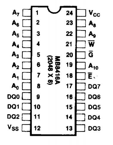
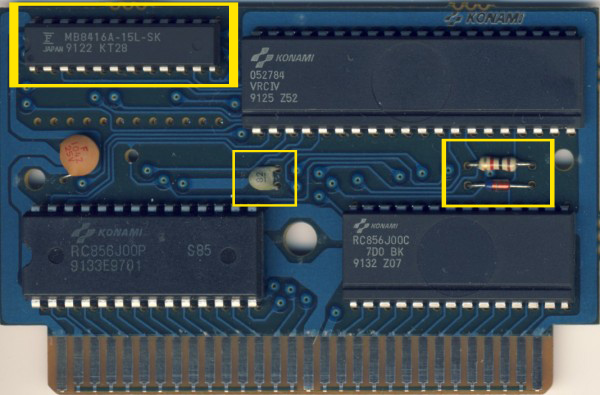
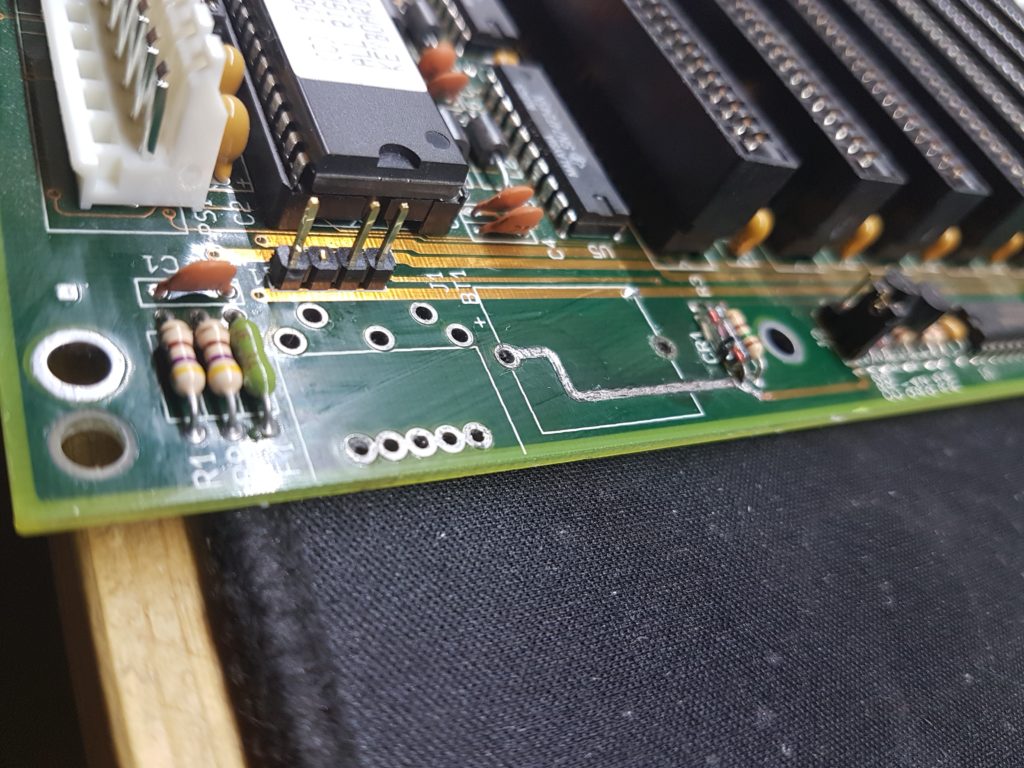
You rewired everything according to the chart and the screen still looks garbled? You may need to remove or add some components to the PCB, namely a 1K resistor, a 1N4148 diode a 2K*8 SRAM 150ns (or faster) IC and a ceramic capacitor.
The SRAM needs to be pin kompatible with the MB8416A-15LZ:
These are the components that need either be removed or soldered in:
Games needing these components:
Crisis Force
Ganbare Goemon Gaiden 2: Tenka no Zaihou
Gradius II
Parodius Da!
Games that need these components removed:
Bio Miracle Bokutte Upa
Racer Mini Yonku: Japan Cup
Teenage Mutant Ninja Turtles I & II
Tiny Toon Adventures
Wai Wai World 2: SOS!! Paseri Jou
I think that should cover all questions 🙂 If not, just drop me a mail through the contact form, I’m always happy to help,
I just stumbled upon a pretty cool youtuber and a problem many of us have faced in the past – finding the perfect continuity tester.
In most cases I use my bench multimeter but a small dedicated device just for this tast would be awesome.
Here comes Leo’s Bag of Tricks!
First of all, his video:
He’s a pretty chill dude and explains his circuit in detail. Definitly worth a watch!
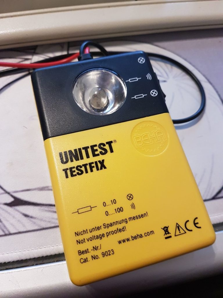
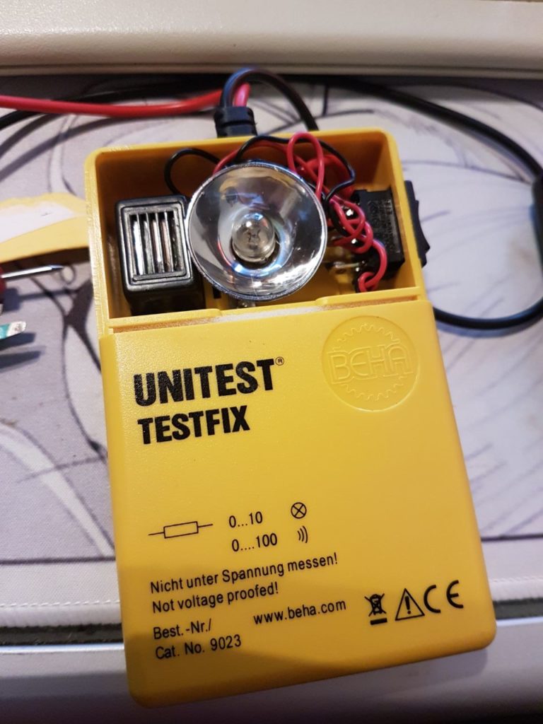
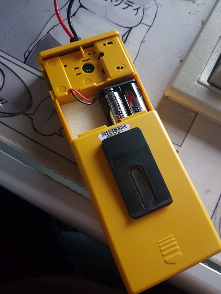
I wanted such a device for myself and plowed through my parts bin. I dug out a primitive tester. It sends 4.5V through the circuit for testing, lighting a little incandescent light bulb and a beeper.
First of all, this is the device:
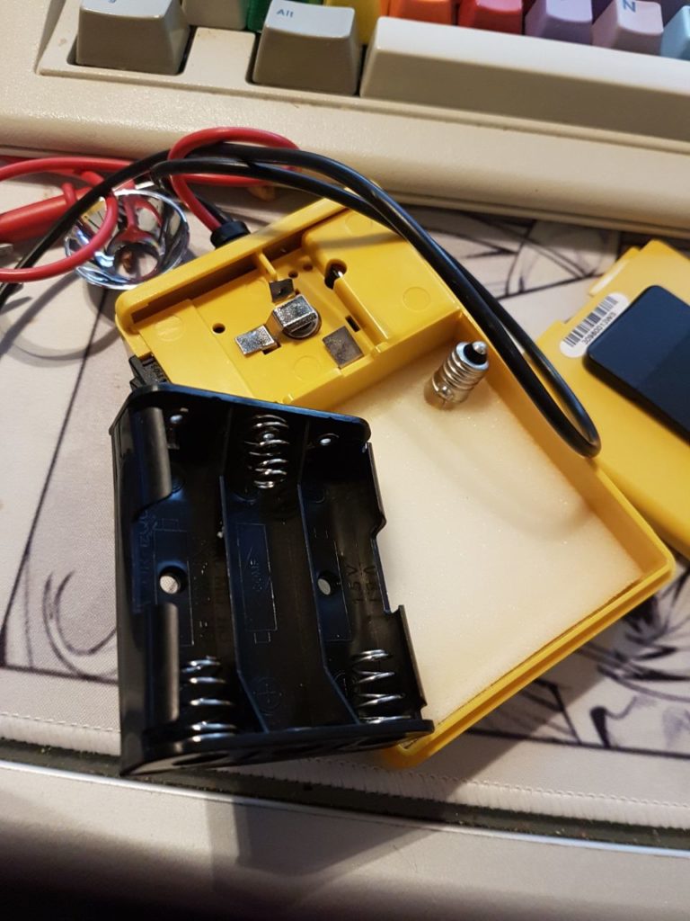
The back compartment houses a replacement bulb and a place for the batteries:
You can pop the front and the back of this thing, thats rather nice:
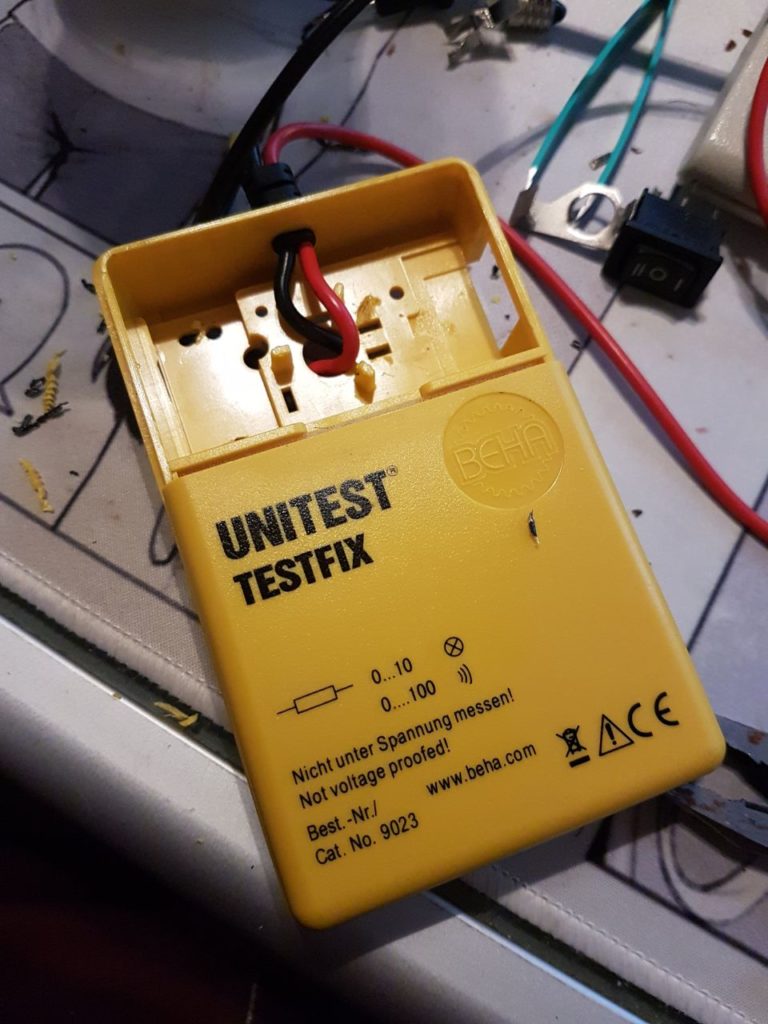
A minute of gutting later…
Unfortunatly the beeper is glued in. I drilled it out but I think you can wiggle and break it if you like.
Eyeballing and meauring the space inside…
~timewarp~
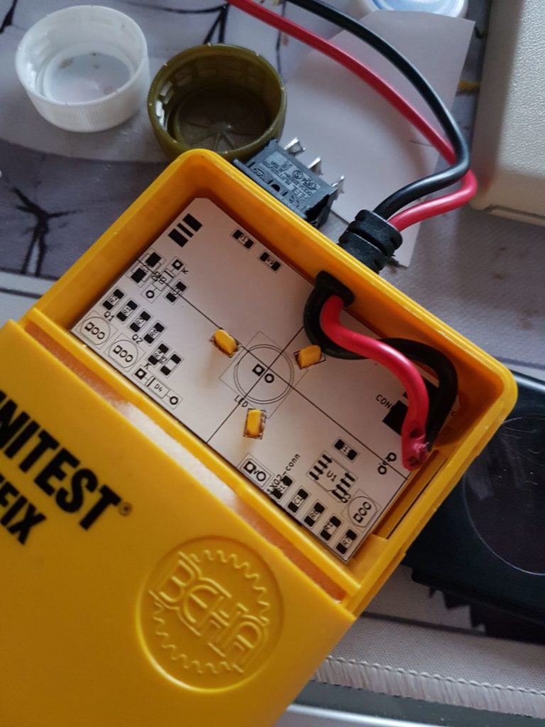
So I just took Leo’s design and placed it inside the TESTFIX 🙂
I’ve left the space for the beeper somewhat flexible so you can fit different beepers in there. The LED in the middle has a 10mm diameter.
The battery holder was changed from 3*1.5V to 2*1.5V. The spare bulb was kicked out 🙂
I put a piece of plastic in the place where the switch originally was – mainly to prevent stuff from getting in there.
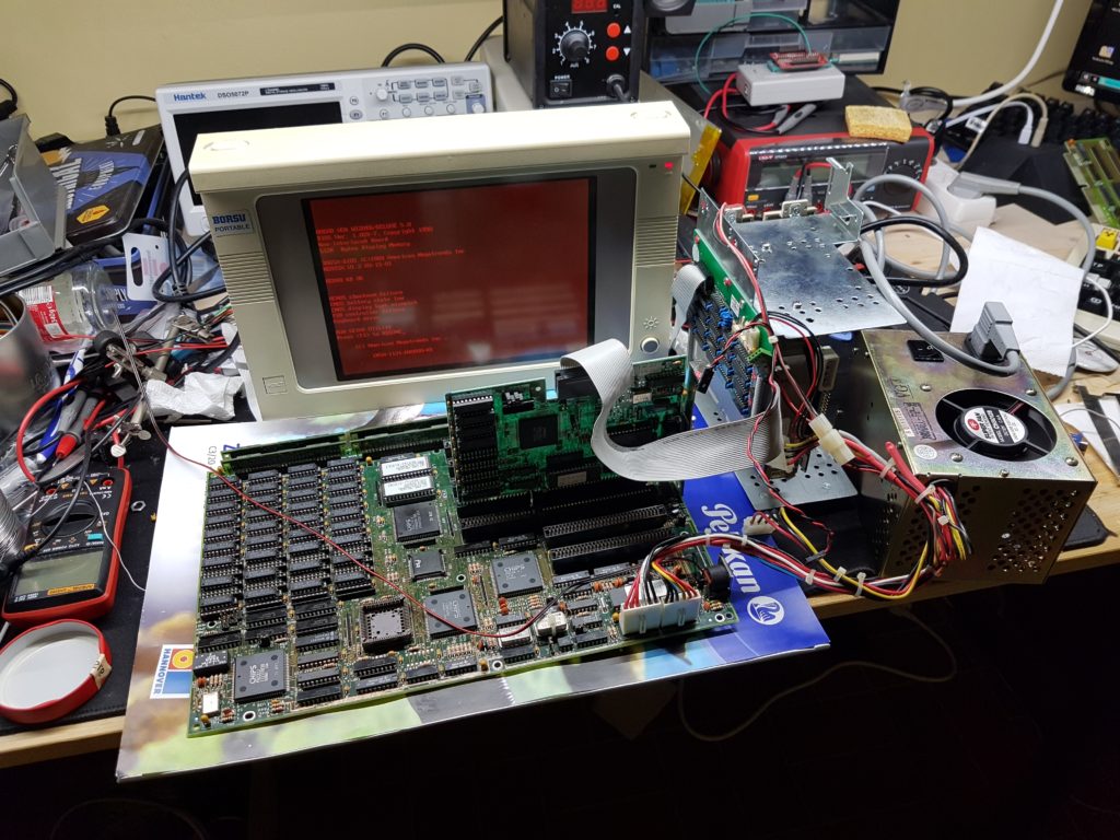
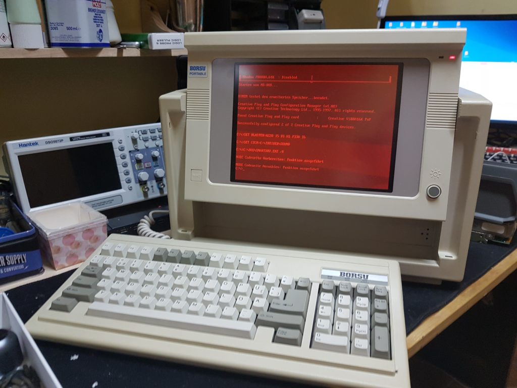
I snatched a nice luggable for a low price. Unfortunatly the auction listing said “untested” – we all now what that means 🙂
So of course – plugging in the AC cord and switching it on does nothing. I took some pictures of the repair for your viewing pleasure 🙂
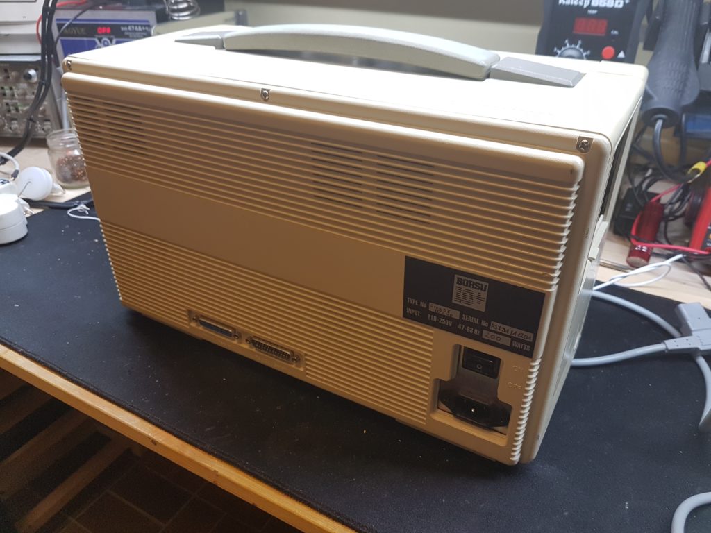
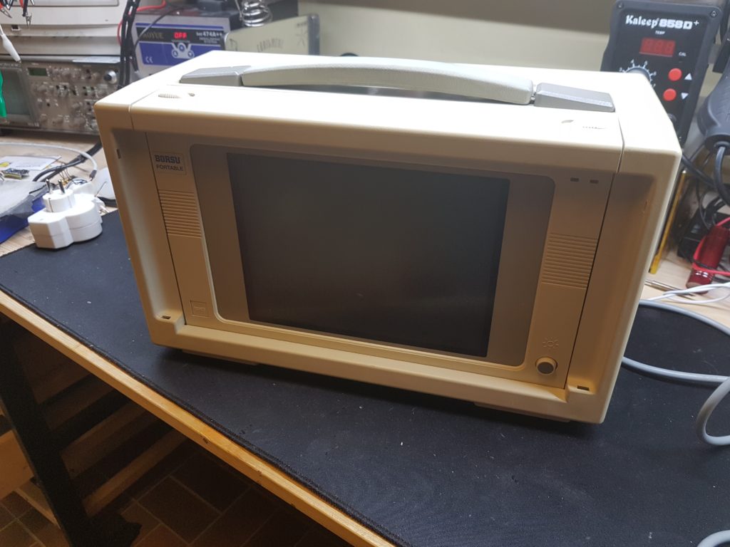
The backside – AC port, beefy power switch, LPT and serial portI popped out the keyboard and tadaa – a nice, clean, uncracked screen with a “brightness” knob. The display seems to be hinged, but you have to manually pull it it and prop it.
The outer inspection relvealed nothing speacial. There is a flap for some extension cards and an old style AT connector for the keyboard. Next I’ll pop it up.
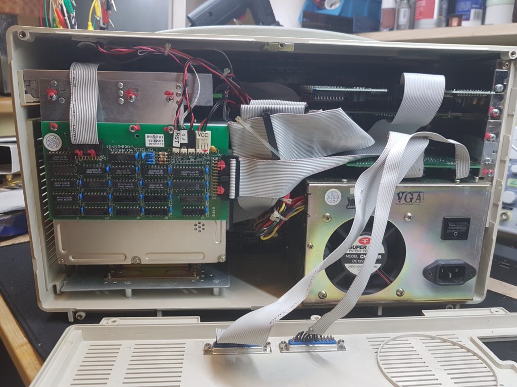
This is a straight up PC in a box, but what exactly did I expect?
The build quality is.. uhm, questionable I guess. No cable management and all the connectors are glued in place.
Quality ™
Next step: Pull all the components out.
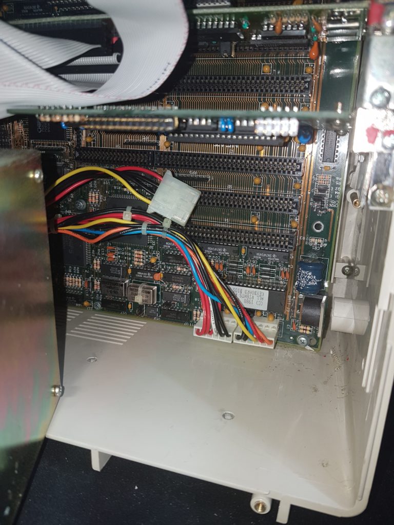
Pulling out the power supply revealed a very sick battery cell
The battery pretty much jumped into my face when moving the power supply. And there is quite a lot of gunk and even plastic spirals rolling around in the case.
Glorious!
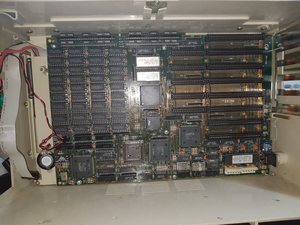
Nicely packed RAM banks, no math coprocessor (wasn’t expecting one anyways) – but overall pretty nice! So let’s get the mainboard out of there and see what the battery did to it…. fingers crossed!
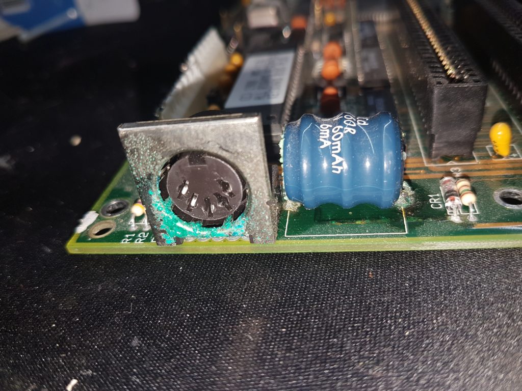
It’s green!
Ew! The keyboard connector sucked up all the batterie’s evil juices. And well, some splatters here and there on the mainboard. Let’s pop the cell out.
*insert stench here*
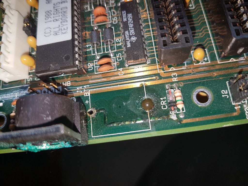
Yep, it smelled just as bad as it looks. The positive rail under tha battery is heavily corroded and some of the thick rail above the nasty blob has been eaten away. Ew.
Desoldering gun to the rescue!
I desoldered the keyboard socket and threw it in highly acidic vinegar and put it after half an hour in an ultrasonic cleaner. It was squeky clean after that.
The positive battery trace was cleaned with a glas fiber pen, same goes for the attacked thick trace. After that I refreshed the exposed copper with some solder.
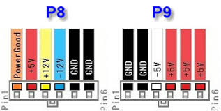
Next up I measured the voltages of the PSU:
The PSU was spot on. So I checked the motherboard and stumbled upon a short between +12V and GND.
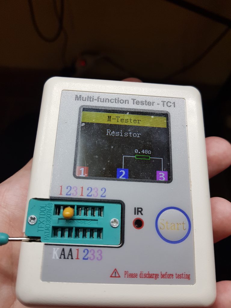
If you’ve been dealing with technology from around the 90s you already know the culprits.. tantalum capacitors!
That should be a capacitor…
The first cap I removed was shorted, oh oh. So I desoldered all of them and tested them – about all of them were dead.
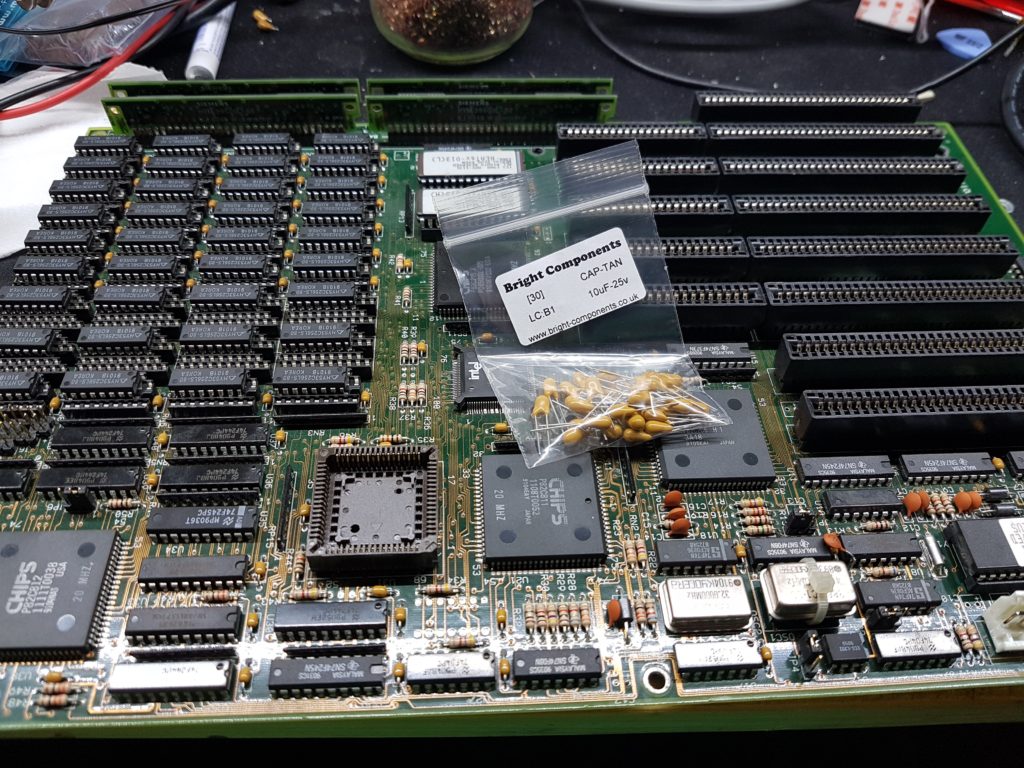
Tasty new tantalums
I replaced all the upright tantalums, plugged everything together and…
See my junk
Woohoo! It booted fine! So let’s see if the hard disk works.
Indeed it did!
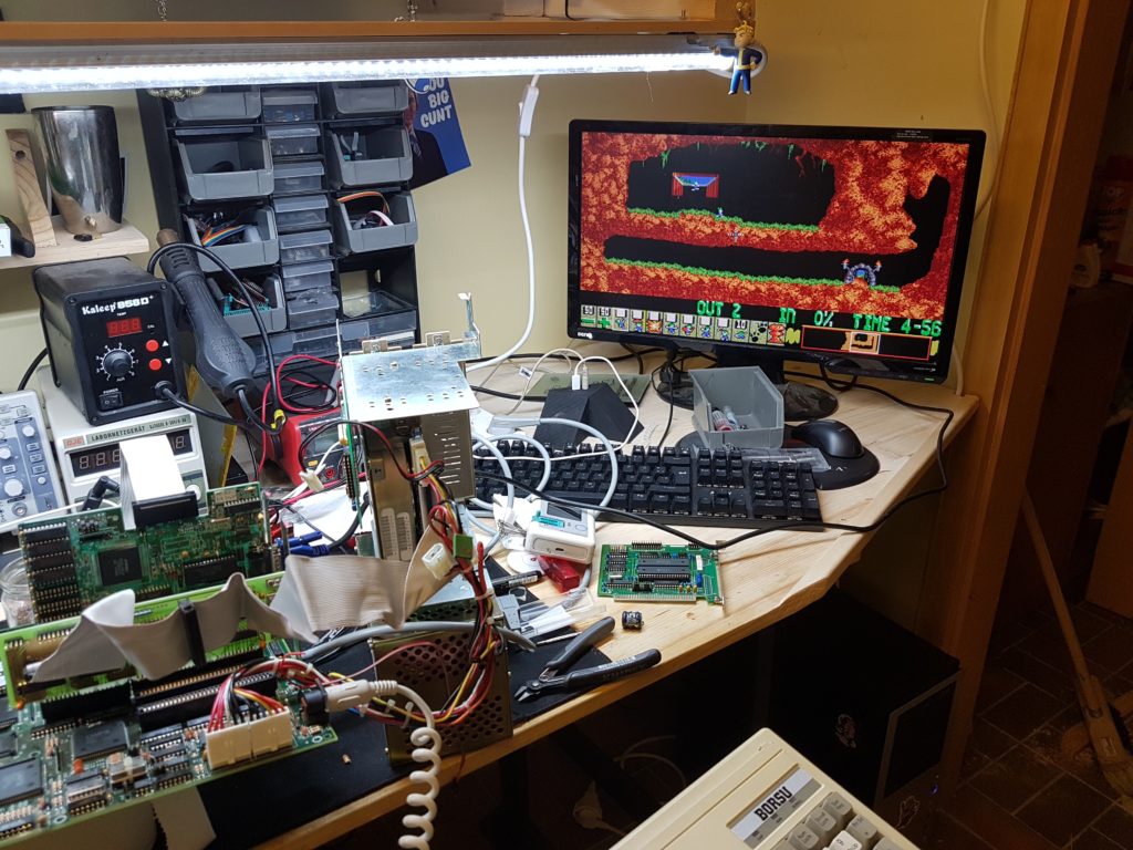
Yep, it is pretty loud but works fine. 20MB capacity full of uninteresting documents and Lemmings! Nice.
So knowing the electronics are okay I had a closer look to the casing.
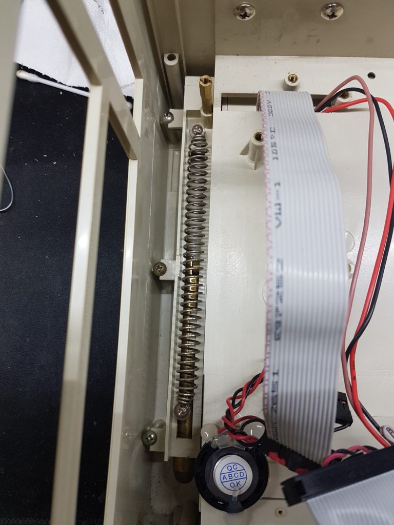
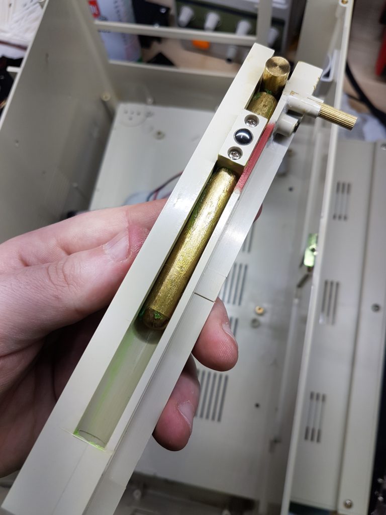
Hinged since 1990
This is how the left hinge for the display looks like.
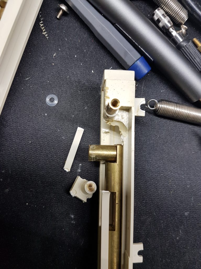
Behold the other hinge
Holy smoke, what happened here? At first I thought it just snapped over time, but there are weird marks all over it – like someone tried to stab it with a knife.
Some goes for the “brakes” of the hinges. Just have a look at them!
I scrubbed them clean and 3D printed the missing bit of the hinge. Unfortunatly all I had at hand was maroon resin, but you won’t be able to see the hinge anyways 🙂
Welded with baking powder and superglue
That green stuff is lithium based grease for increased hinge slipperyness, if that’s a word.
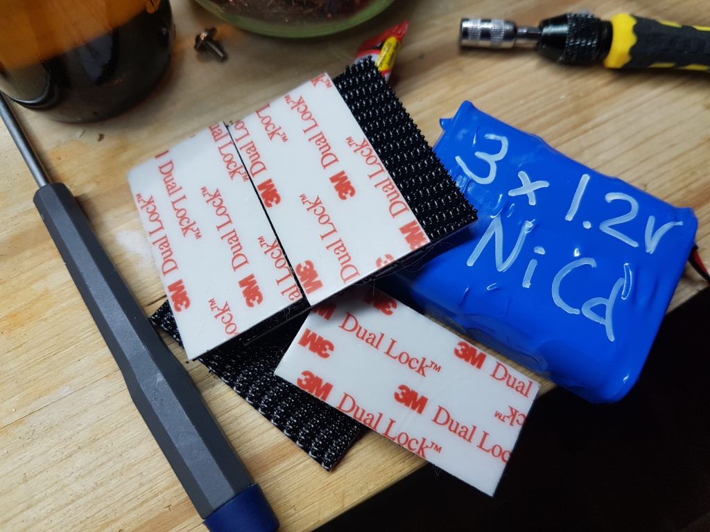
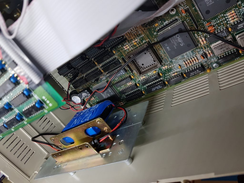
The desoldered battery was replaced with three industry grade NiCd cells and velcroed to the HDD caddy.
This is your new home
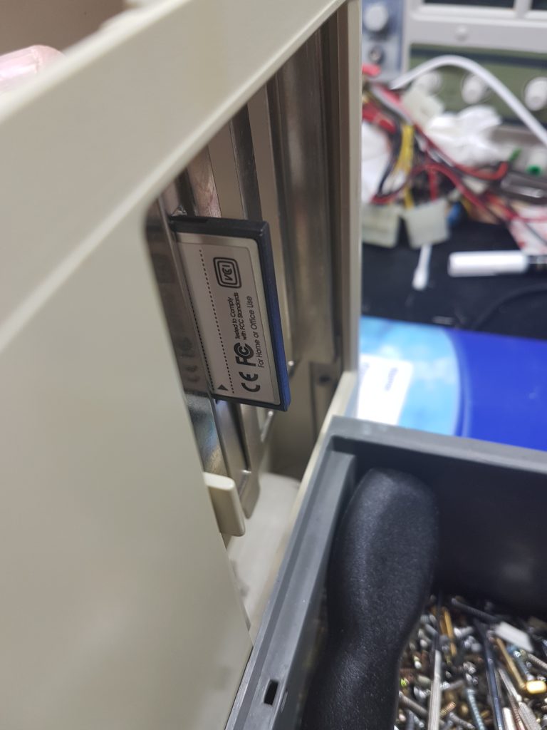
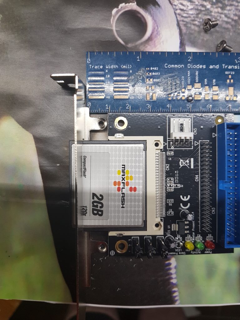
The HDD was replaced with a CF card mounted to the expansion bay for easier access.
Wait.. will this even fit?
Yeah well, the CF card is sticking out and the sliding door for the expansion cards won’t close this way. Unfortunatly I forgot to take a photo of it, but I 3D printed an adapter to move the CF card further in.
The jumpers on the CF adapter were already set correctly – to a single master disk.
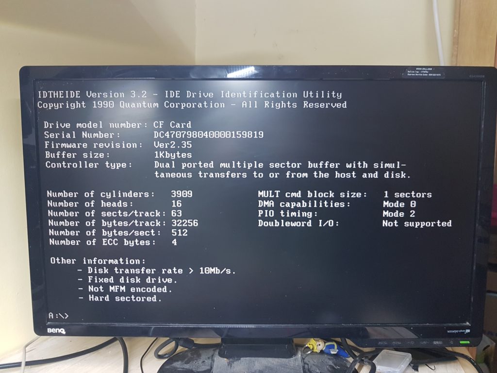
So after mounting the CF card I tried to boot the machine. Well, the BIOS will detect the CF card automati.. no. No automatic detect for HDDs on this BIOS. So I googled and found “IDTHEIDE” (download here) – a tool that will find the correct cylinders/heads/sector count of an HDD.
I tried to put the program to a floppy disk and boot from it – no dice! The floppy drive was pretty much dead. So I tried a gotek flashed with flashfloppy and put an image of the floppy on it.
Tell me your secrets
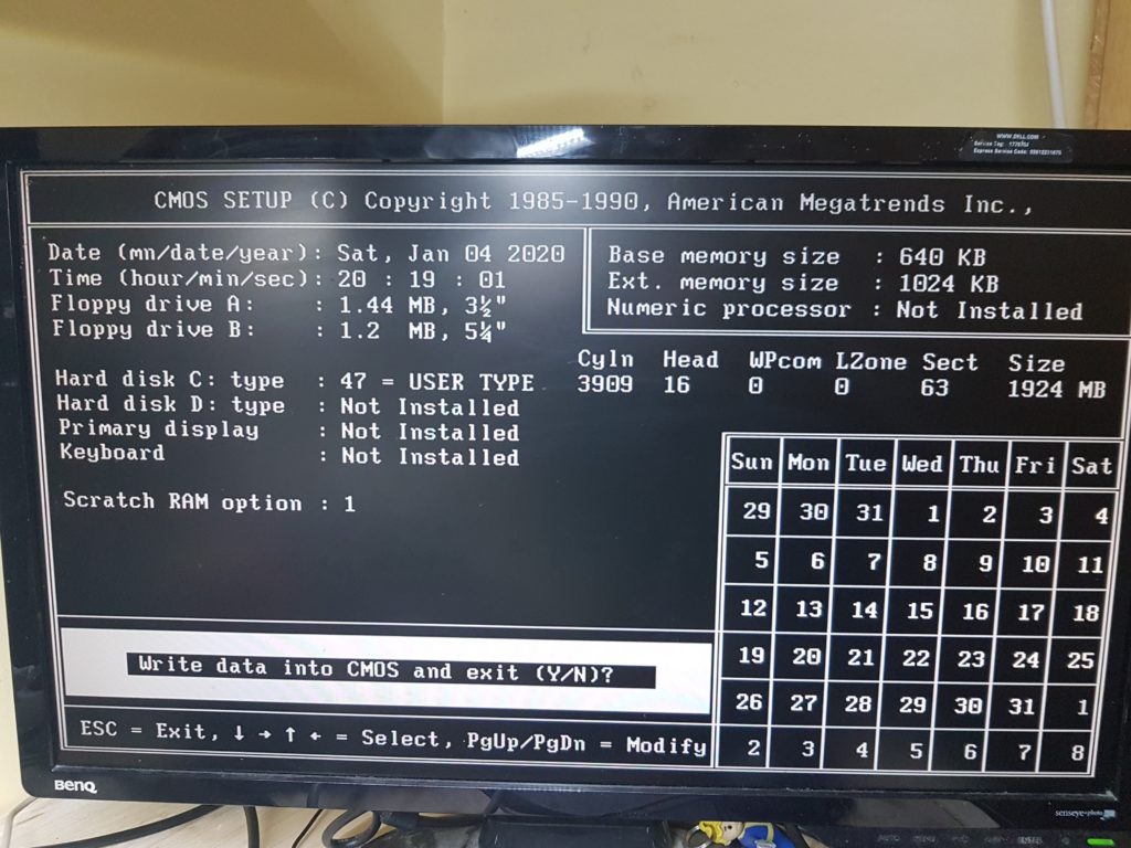
The tool worked perfectly! It detected the HDD straight away and all I had to do is to write down the values and put them into BIOS.
Y2K? No problems here!
After entering the correct values the CF was recognized correctly. Next up I installed MSDOS6.22 I’ve got for free from the web archive. I backed up Lemmings from the original HDD and put it back to the CF card – it worked! But no sound, meh.
So I shuffled through my stuff and found a nice Sound Blaster 16, put it in and installed it. No problems there! Booted up Lemmings again, this time with glorious sound!
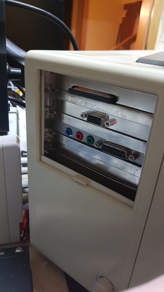
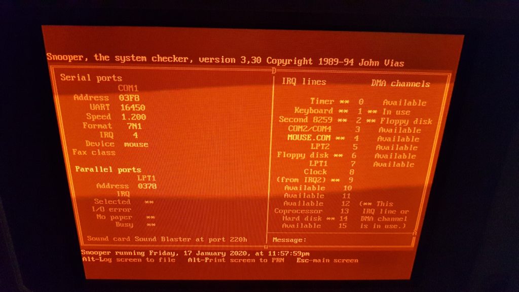
CF, VGA, Line-In – Microphone – Speaker Out – Game Port
There was a serial Mouse included in the auction for this machine. Plugged it in, installed the Microsoft Mouse Driver 11 (if I recall correctly) and booted Lemmings again to test it. Worked fine!
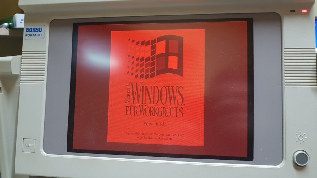
I installed Win3.11 just for fun – it runs okay but sometimes crashed. Guess it wants more than the 2MB RAM the mainboard currently has.
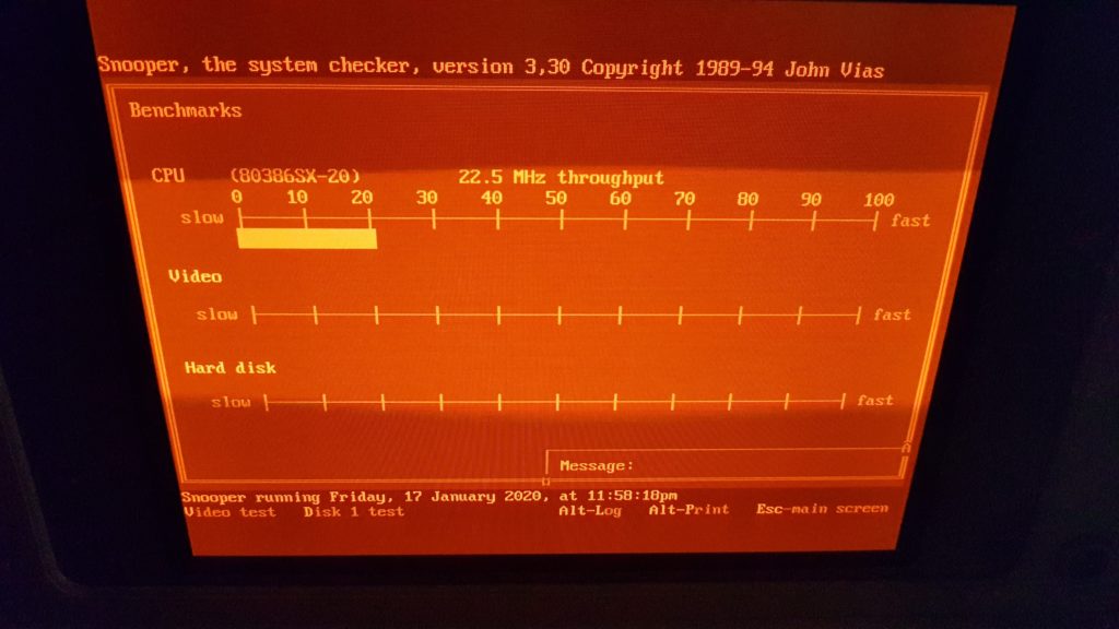
I like the orange glow
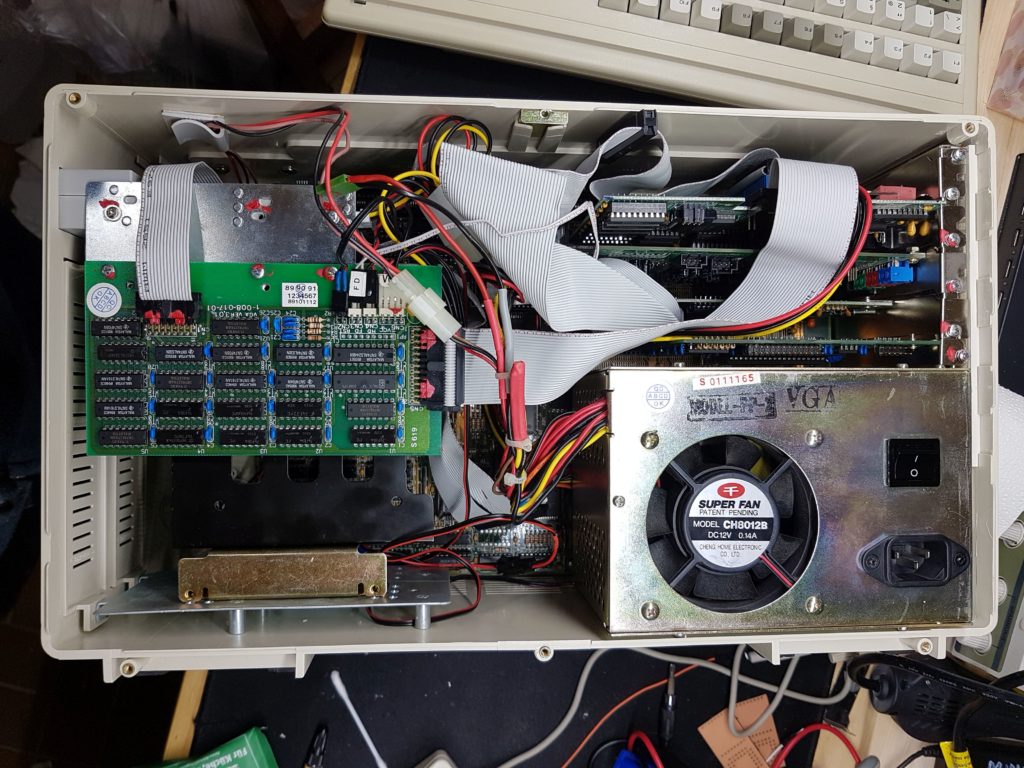
Lets have a last look at the innards before closing this beast:
Still just a PC in a box
I had to install an HDD adapter plate for the now missing HDD. An installed HDD gave structural strength to the assembly to the left. If left out, the assembly to the left tends to sink down.
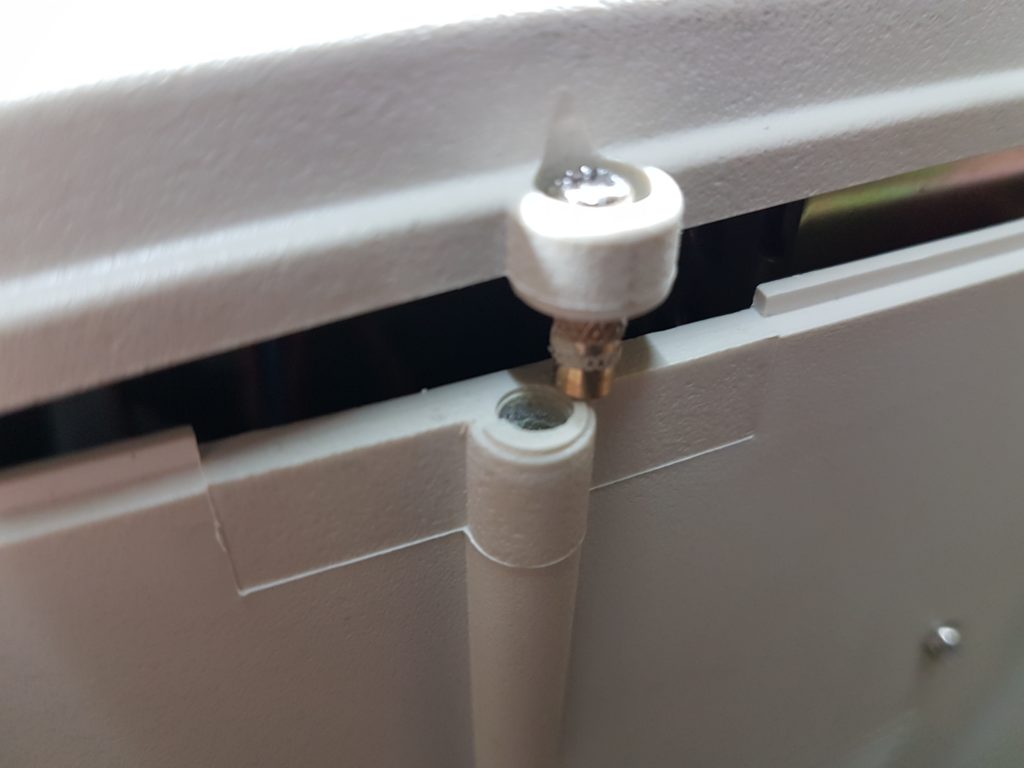
Finally I put the backplate on and screwed it down.
For real?
Sheesh. When screwing the backplate down one of the inserts lifted straight out. Glued it down with epoxy after that.
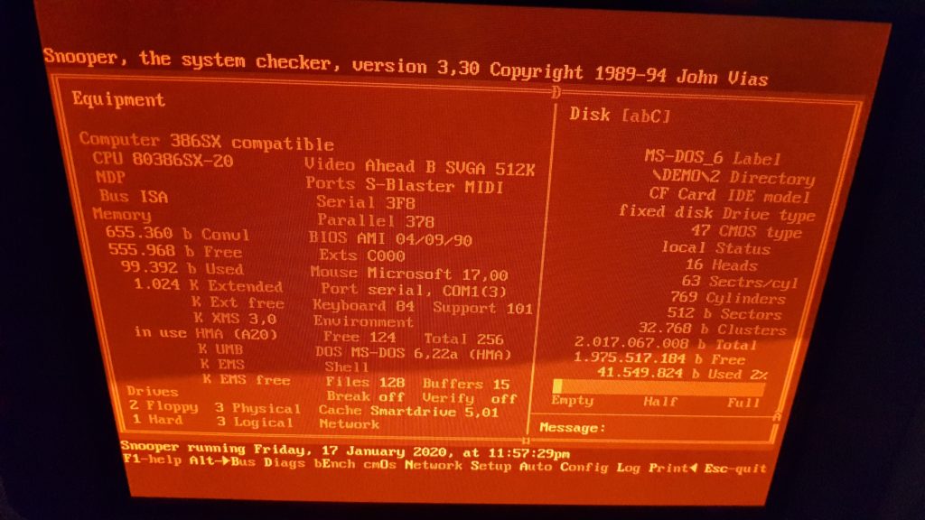
At least, this beast was finally done. Next up are some specs.
I’ll print out the BIOS settings and put them between the screen and the keyboard. Just in case.
PS: I tested tested the RAM and pretty much everything else 🙂
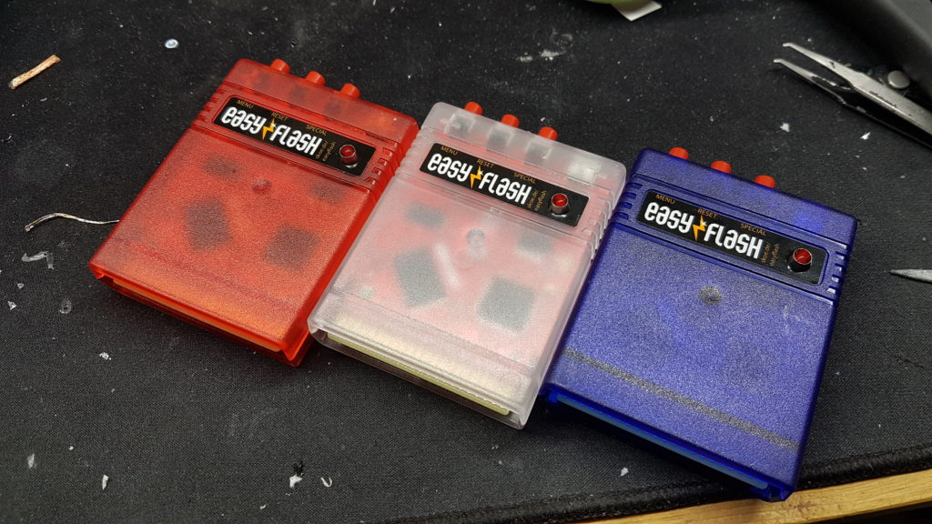
This is just a quick one. I wanted one of these fancy easyflash cartridges for the C64, so I built one and changed some stuff and added a fuse. This post is mostly to keep the project files ready for anyone to download and reproduce the cartridge :o)
Please don’t mind my dirty desk 😉
That’s what the cartridges look assembled. They sport a fancy led on the front and big buttons on the top for my clumsy fingers to operate.
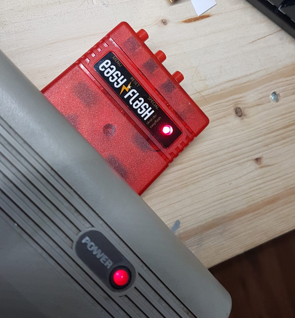
Fancy LED in action
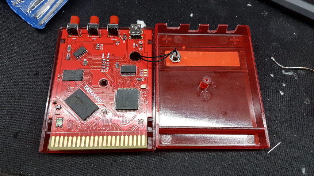
The LED is wired through the pcb to a footprint. The hole in the pcb makes room for the LED socket. You can wire a LED normally if you like, the footprint is between the USB port and the SPECIAL button.
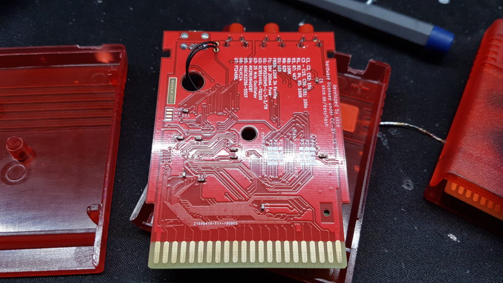
I printed to bom to the back, for easier repair. The programming pins for the cpld are also available, just in case you need them for debugging. In addition to that the pcb is now protected by a fuse.
The gold plated connector is chamfered 45° so plugging it in is a big easier on the connector.
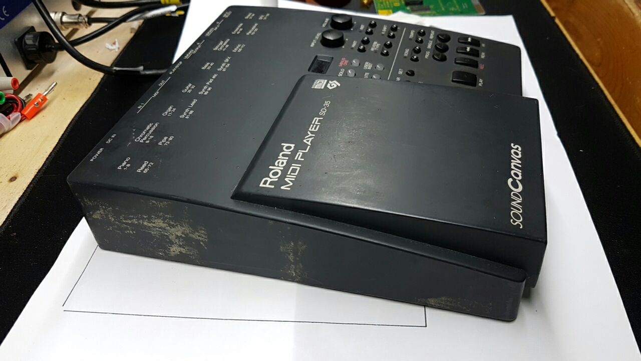
I was able to score a sweet sound canvas for my PC setup. Unfortunatly it arrived in a non working order 🙁 But hey, where’s the fun without a nice little repair?
First off – an outer inspection:
Is that tape residue..?
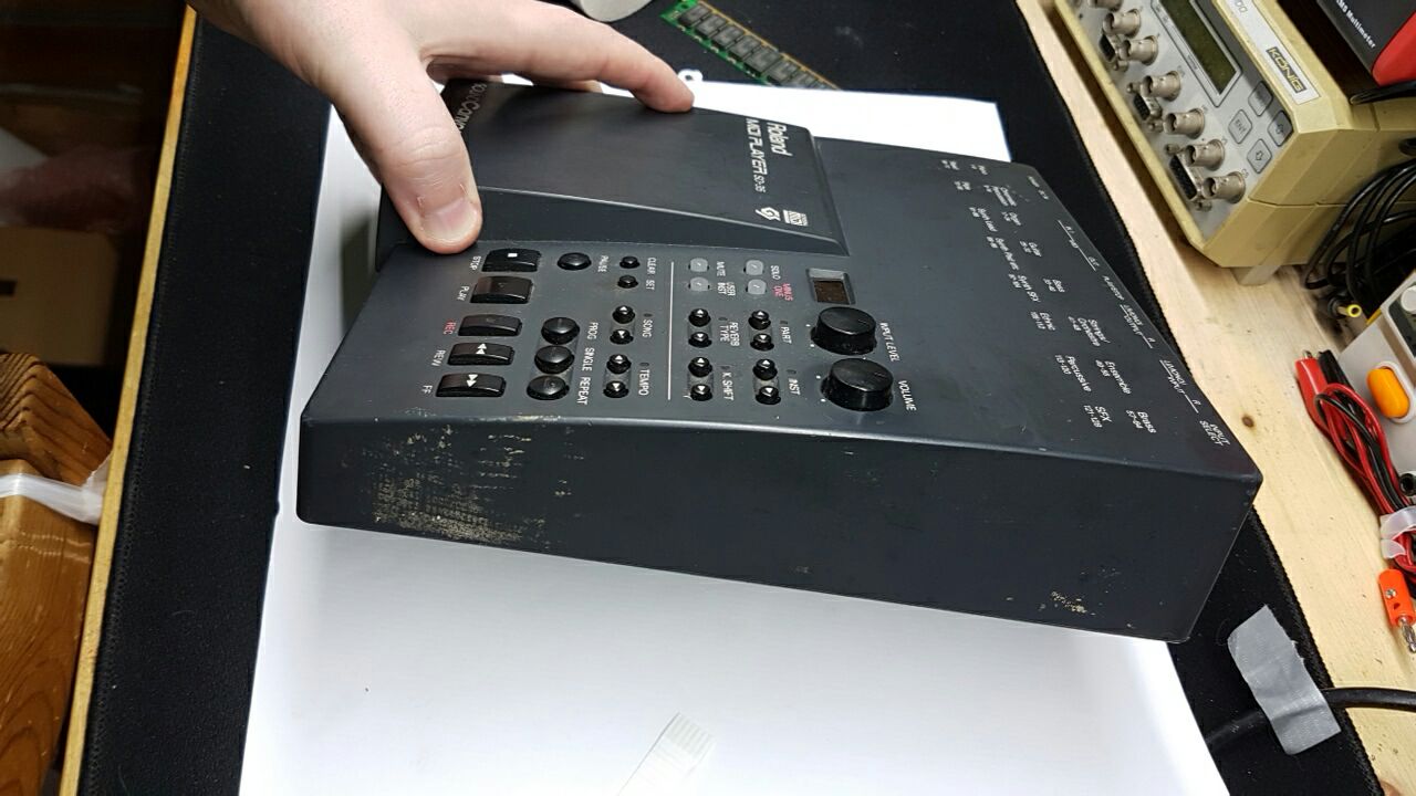
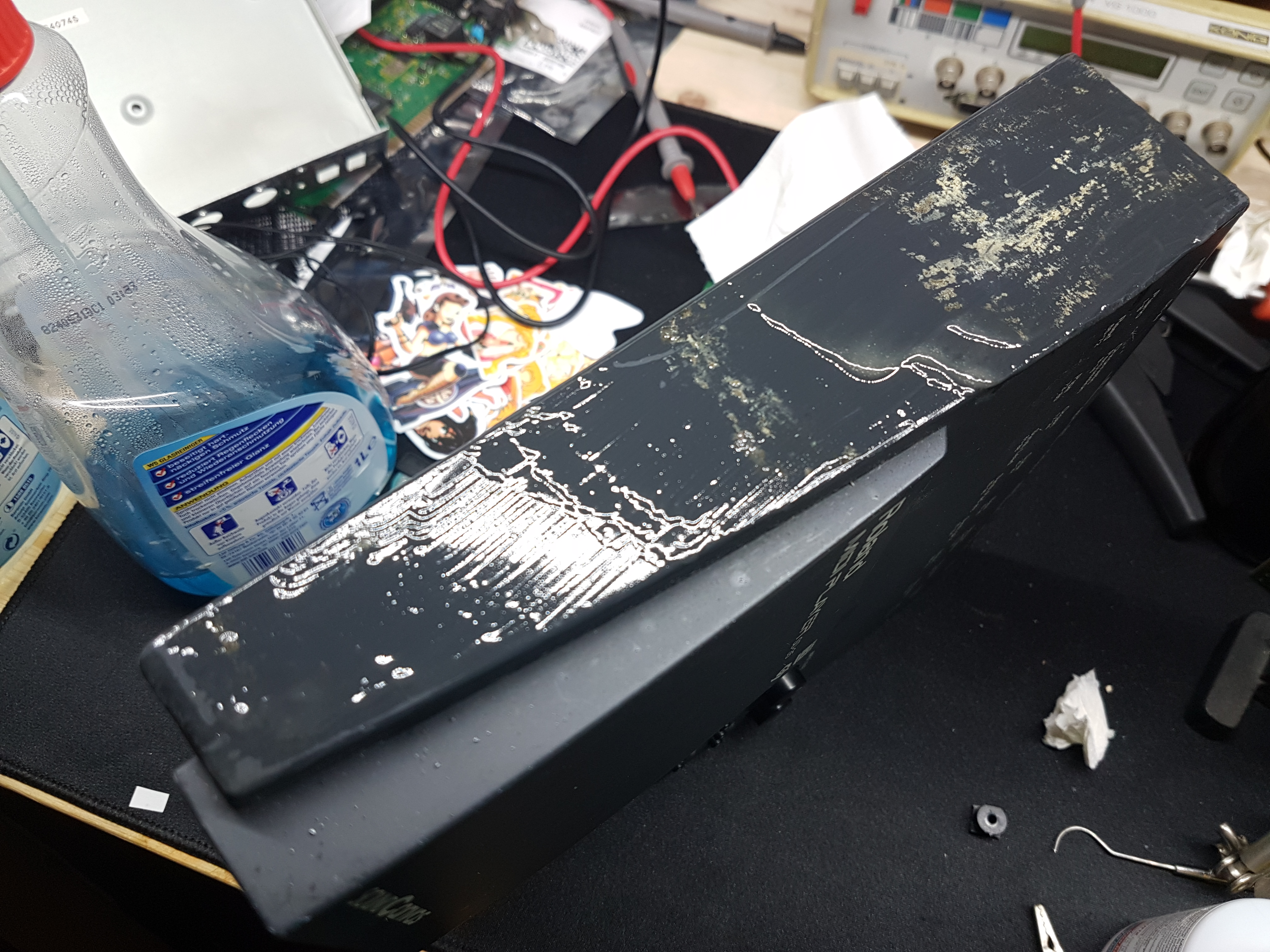
The whole thing seemed to be wrapped in tape sometime in the past. The residue is rock solid. Let’s turn it on it’s back…
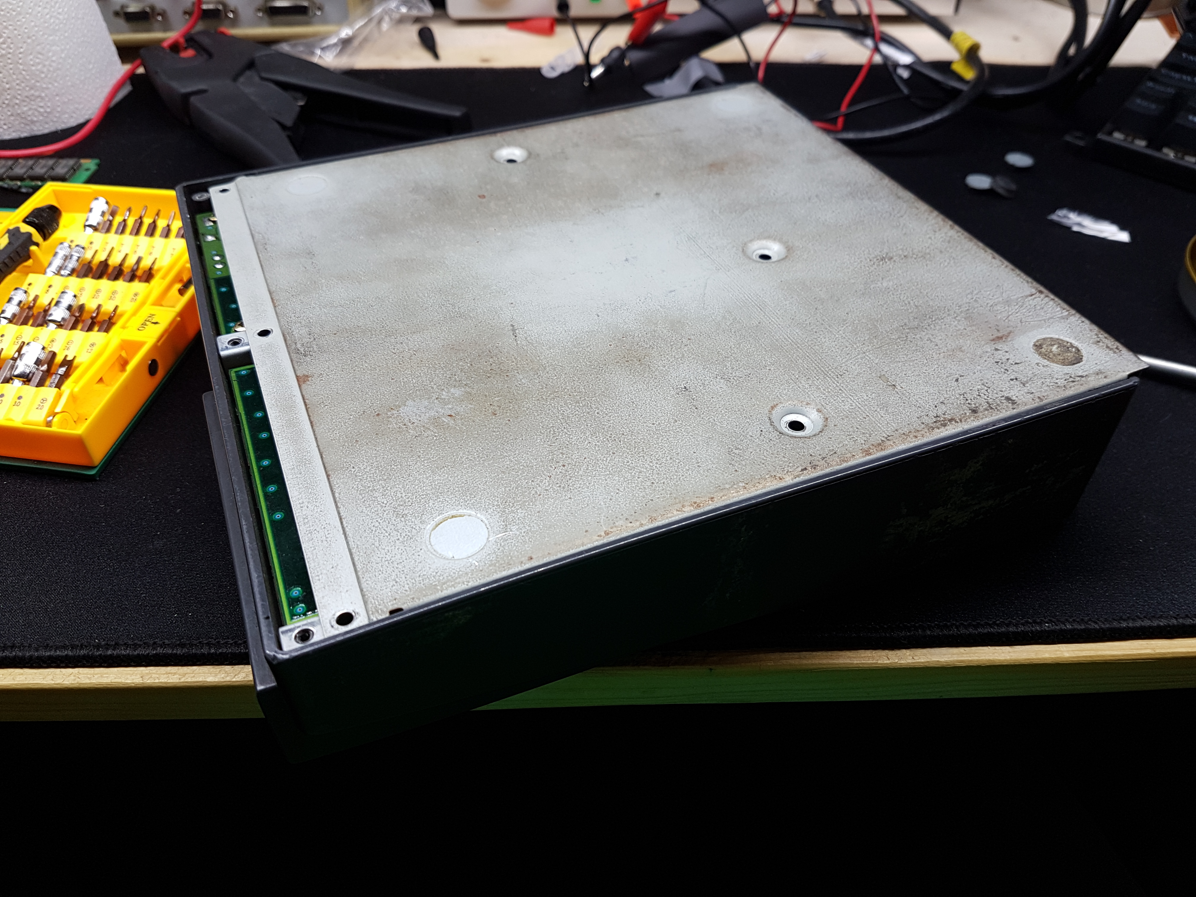
Yikes!
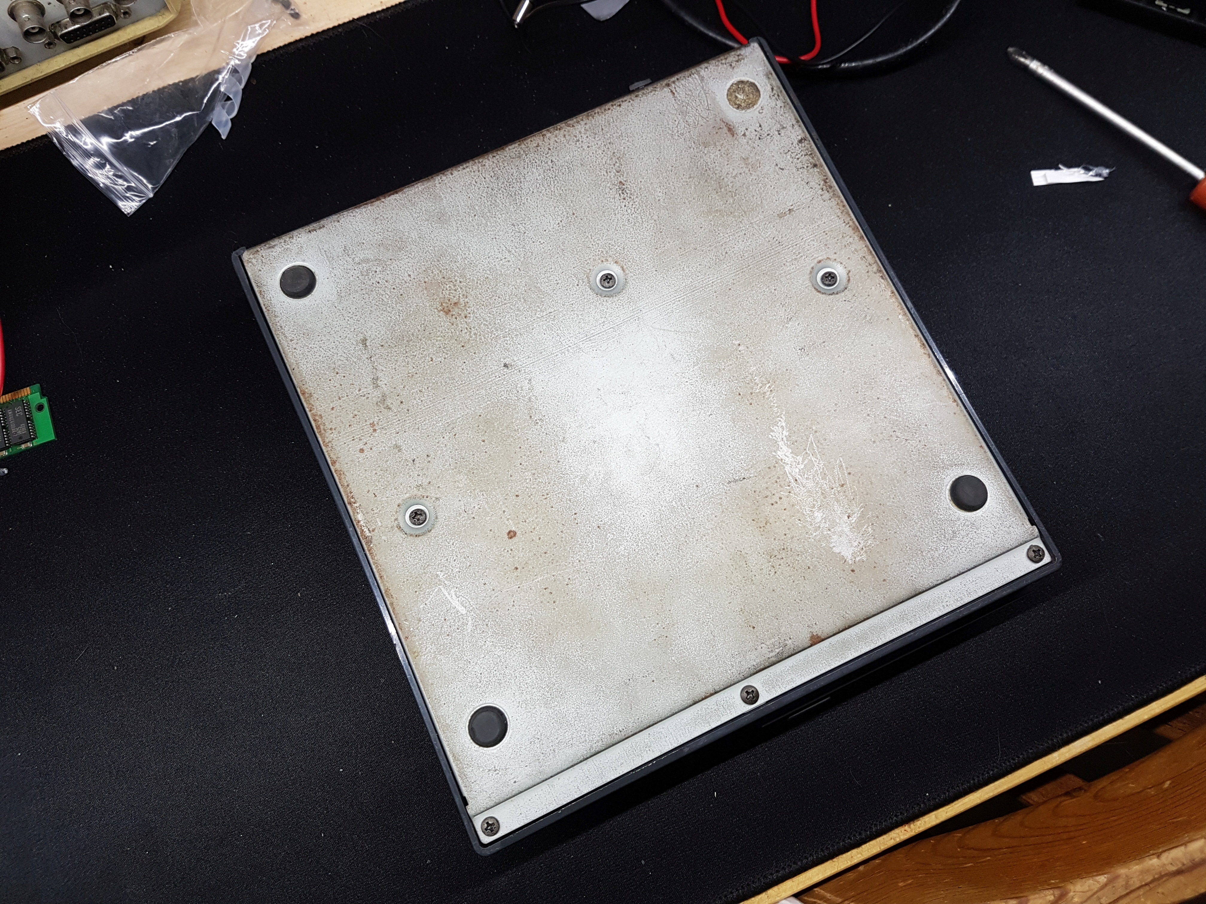
I was a bit shocked – but the rust is just superficial. And one of the rubber feet is missing, no big deal. At this point I tried to power it and switch it on – but to no avail. It’s dead 🙁
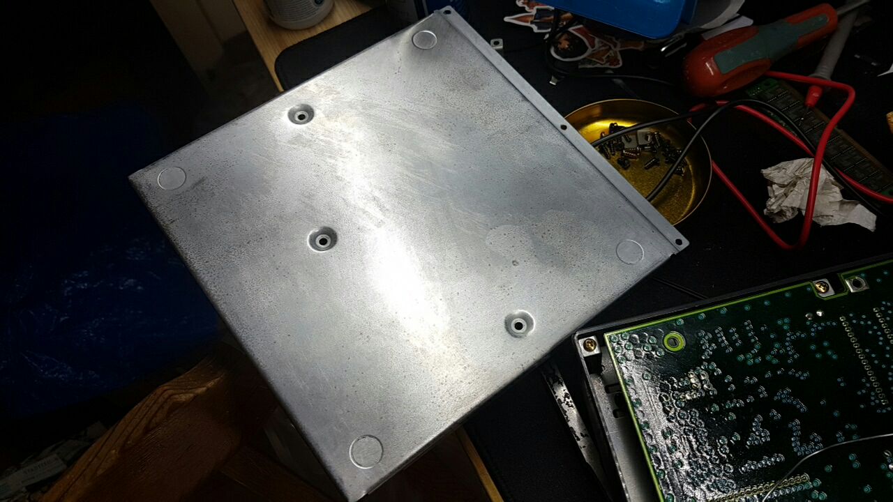
While attempting the repair I let the rusted bottom plate soak in vinegar acid.
Removing the screws pops the beast openSee you in an hour or so 🙂
Back to the sound cavas!
Lookin’ fine
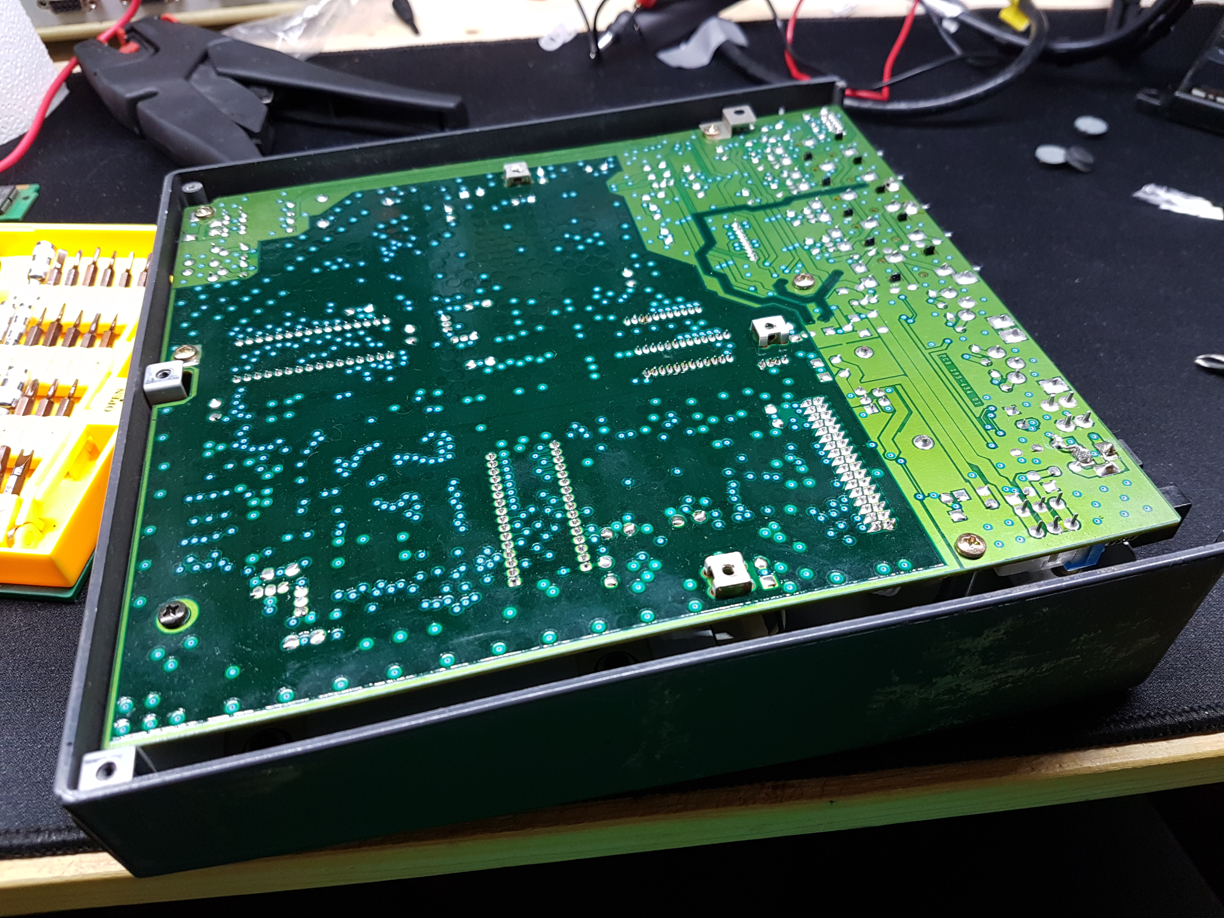
So, no acid damage on the underside. I’ve read in the manual that the device settings are stored in a battery. So I braced myself for some corrosive damage. Try to pop the hood and take a peek.
Sweet! The battery backed storage relies on a lithium cell (right hand side, in a nice cell holder) which seems to be fine. I removed it anyway, since its most probably dead.
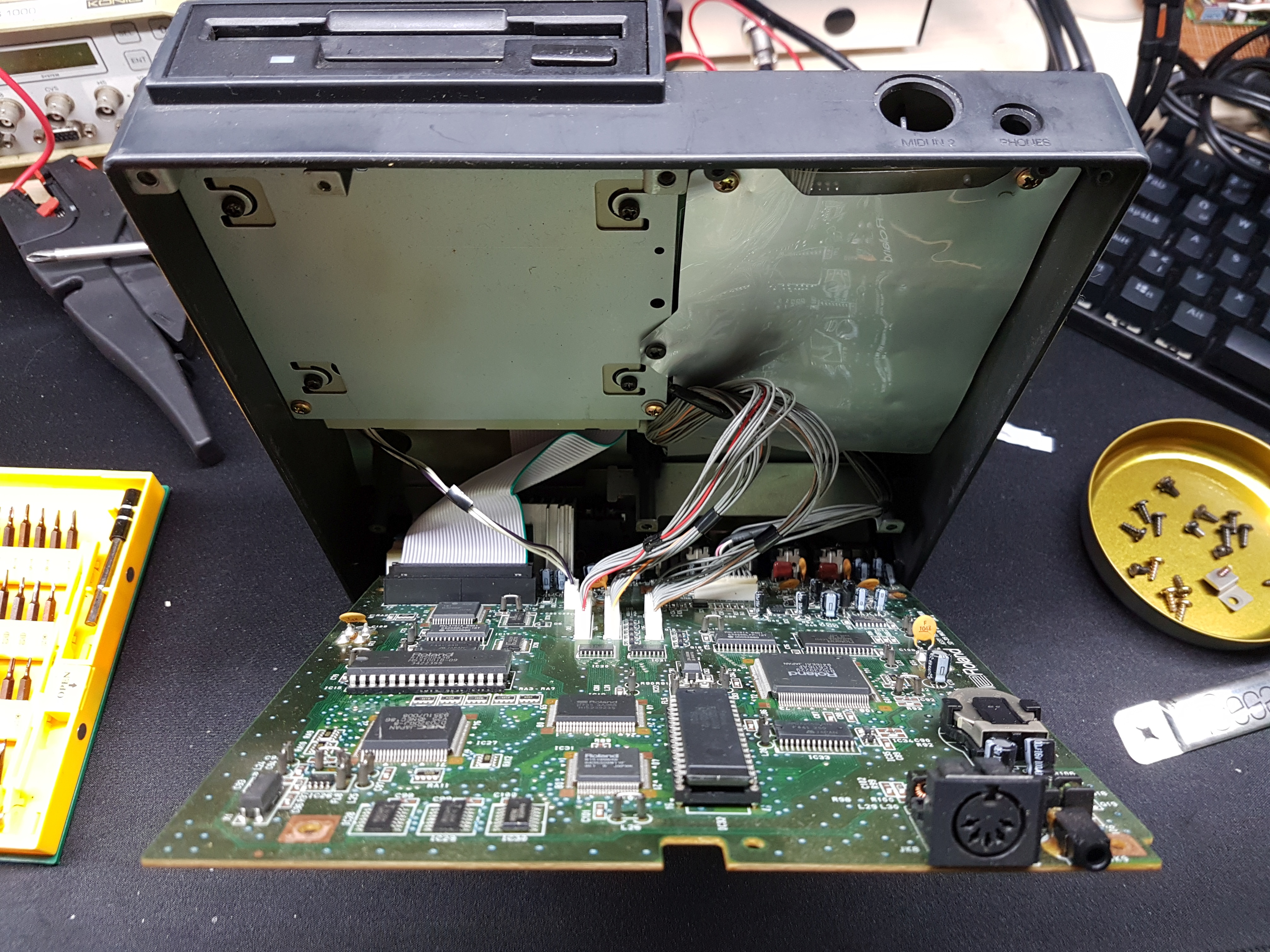
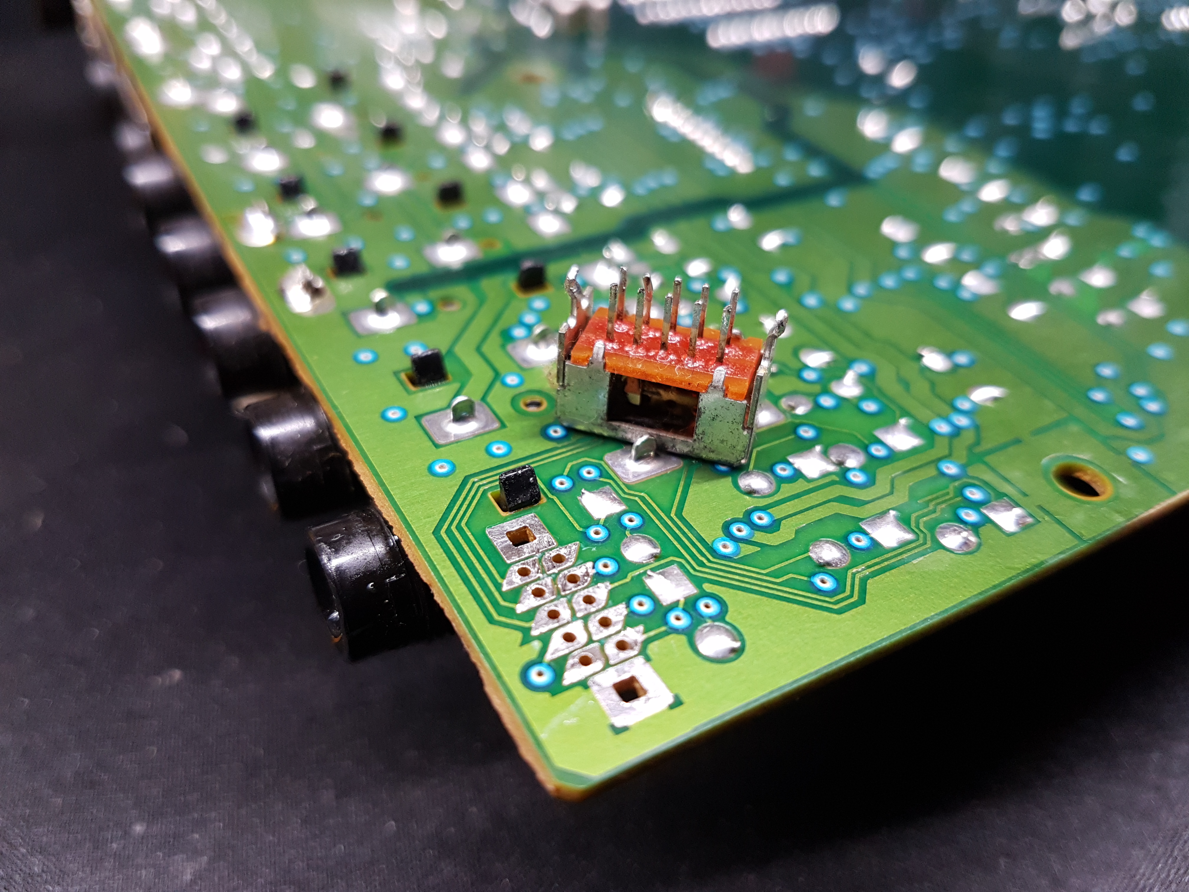
Next up was another visual inspection. So I just unplgged all the plugs and had a look around. Just checking for anything obvious, broken traces, bulging capacitors, all that stuff.
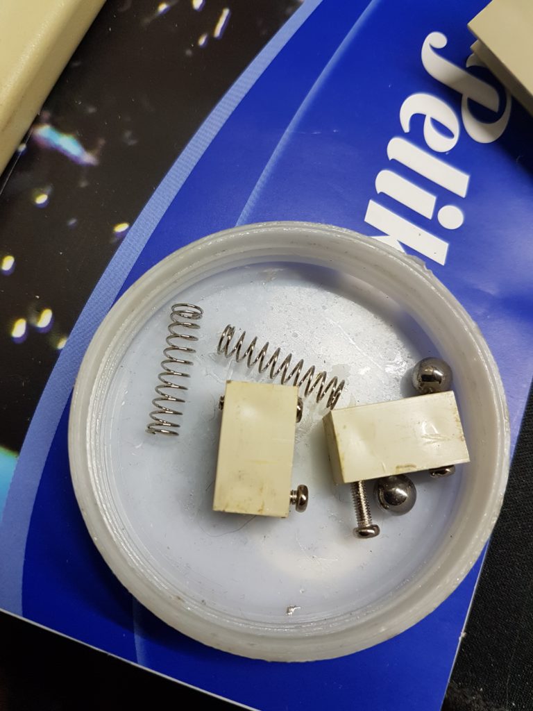
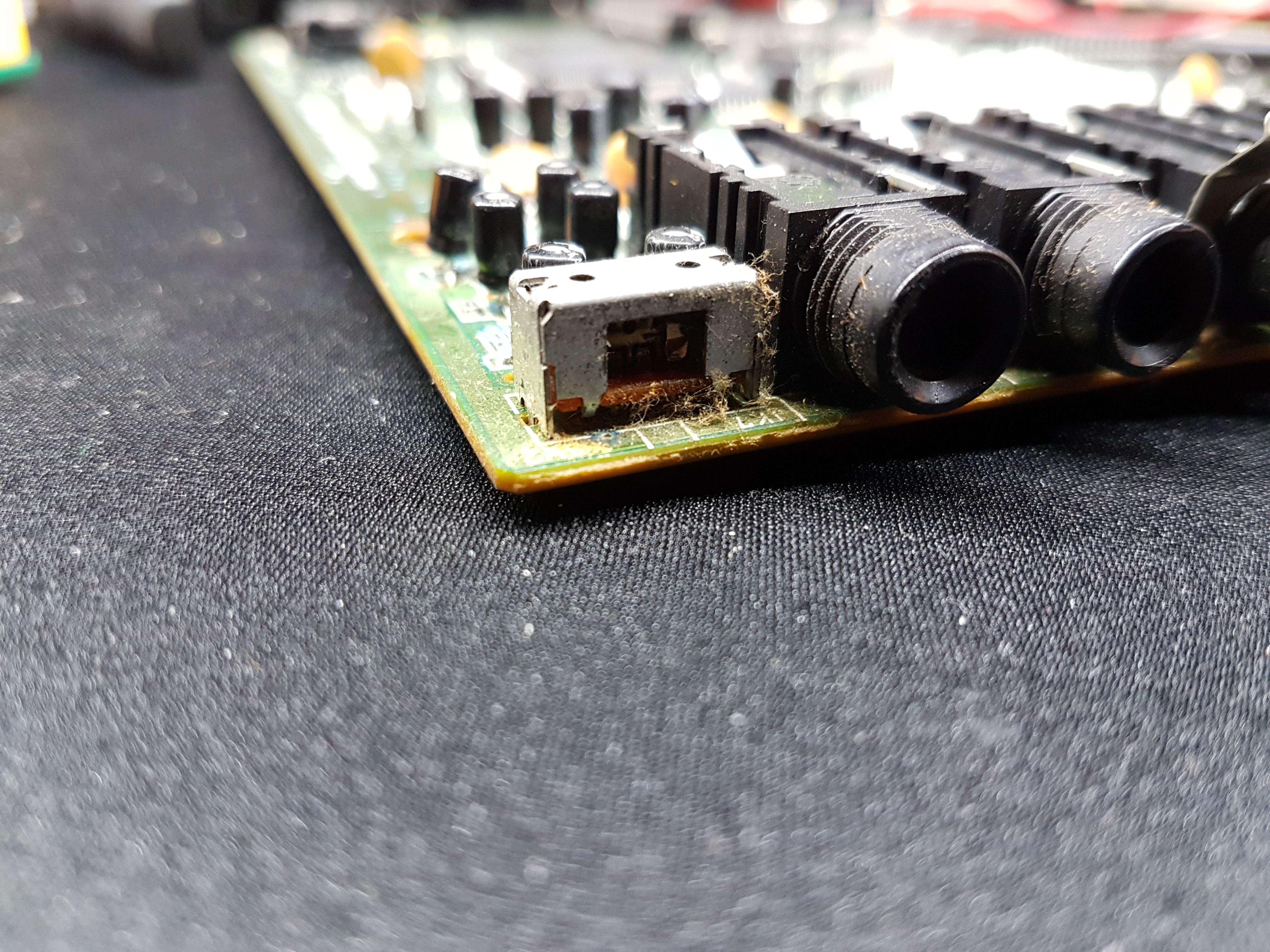
This is the input selection switch. Seems to be dead and hollow. More about that later.
RIP
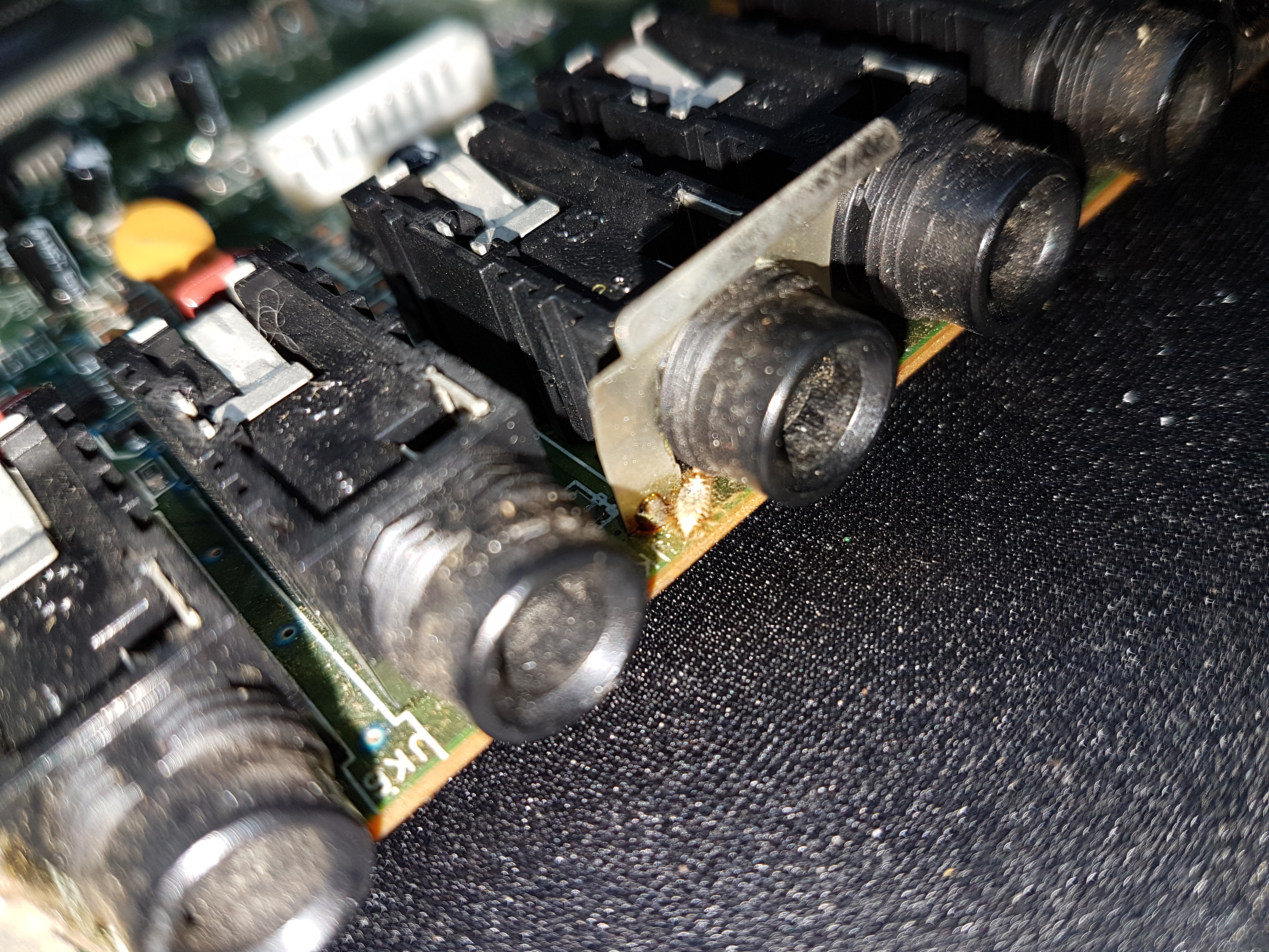
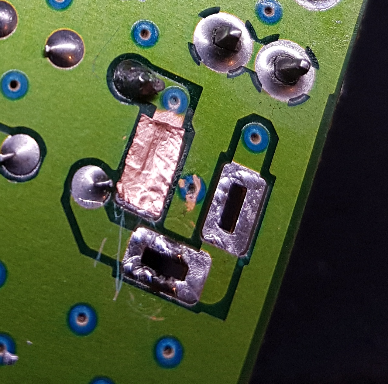
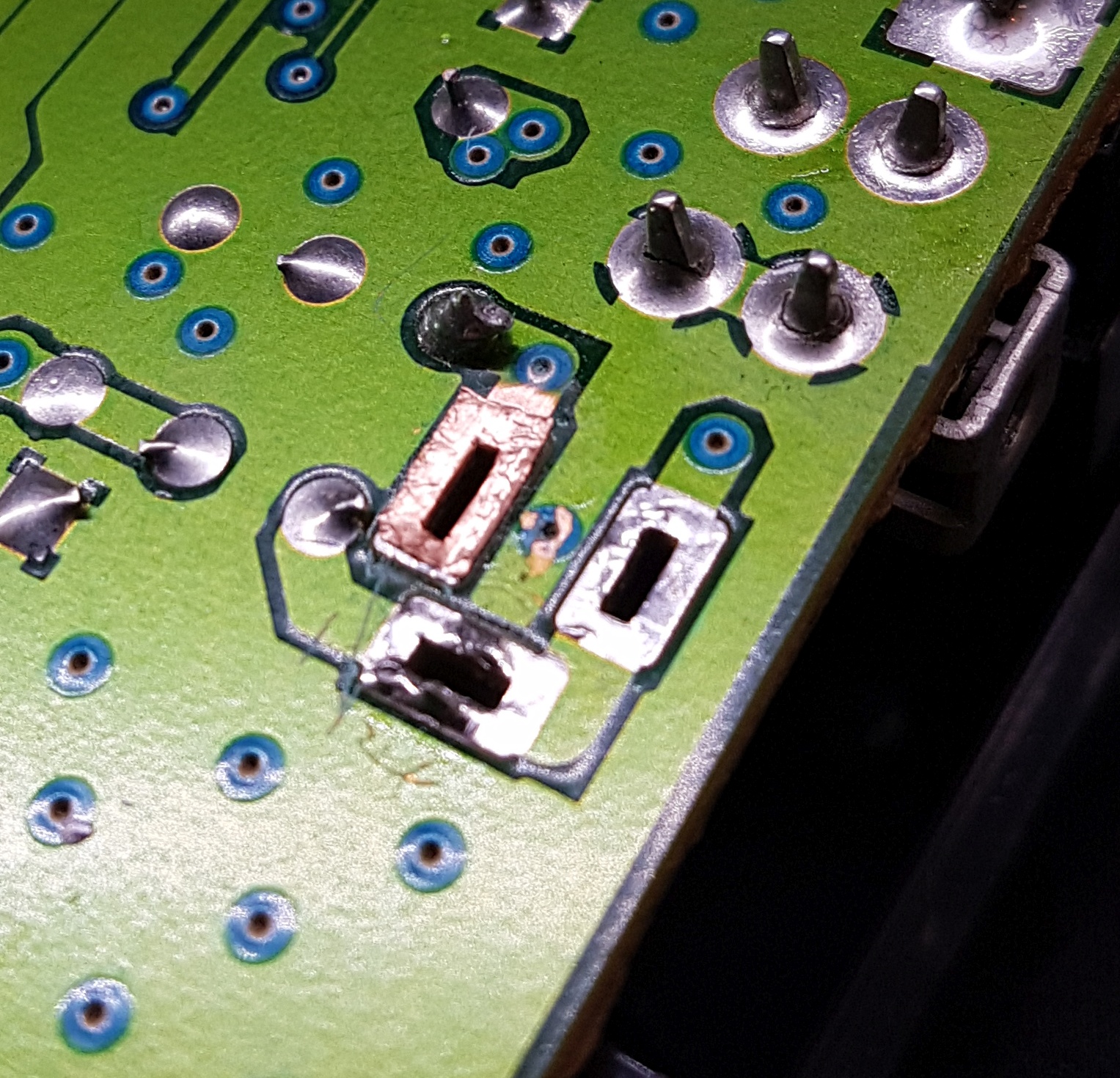
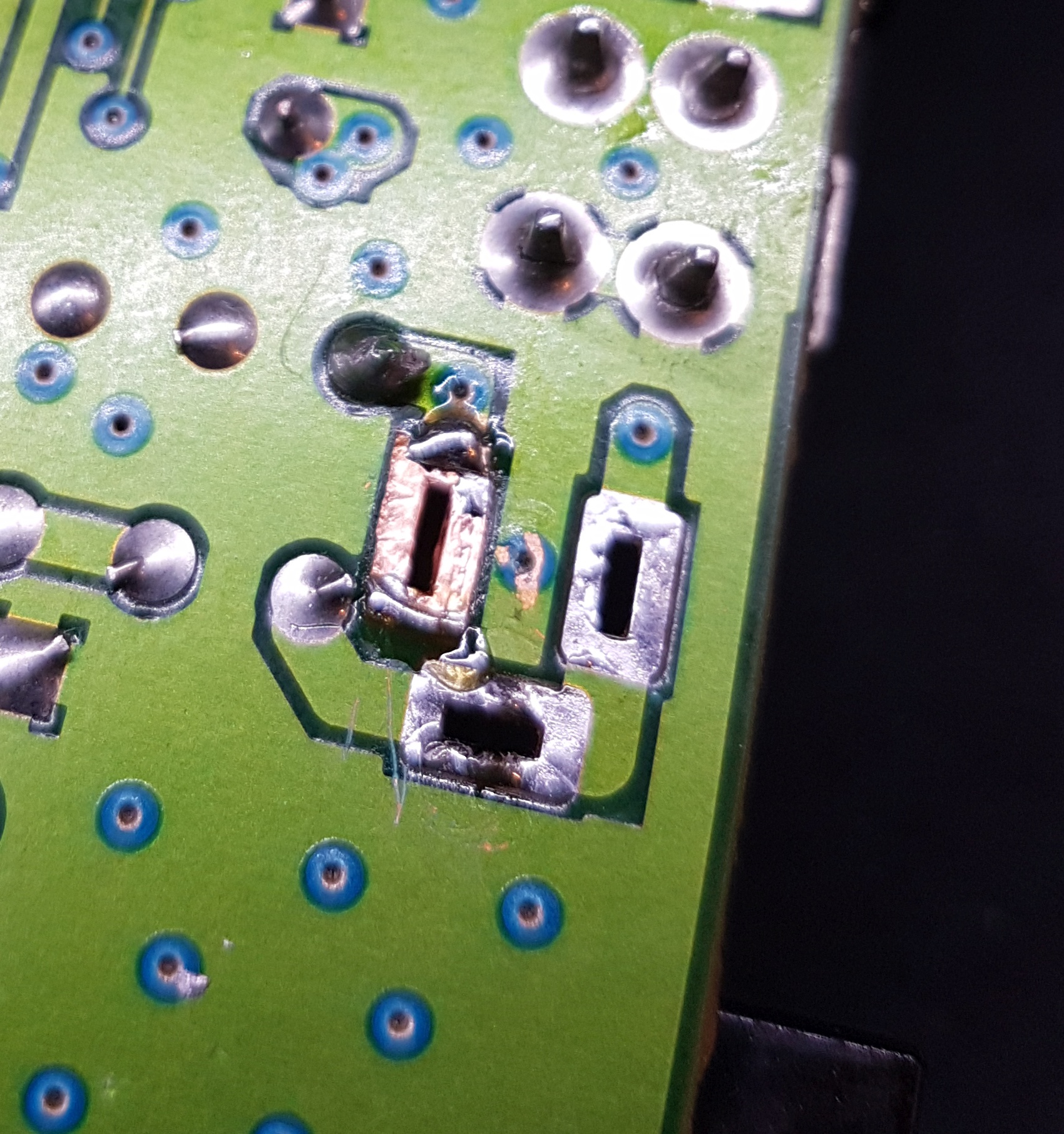
Always funny to find a literal bug! In addition to that I found the power input jack had cold joints and had a bodge wire dangling around.. Unfortunatly I don’t have a picture of that, just took one after removing it and some while the repair.
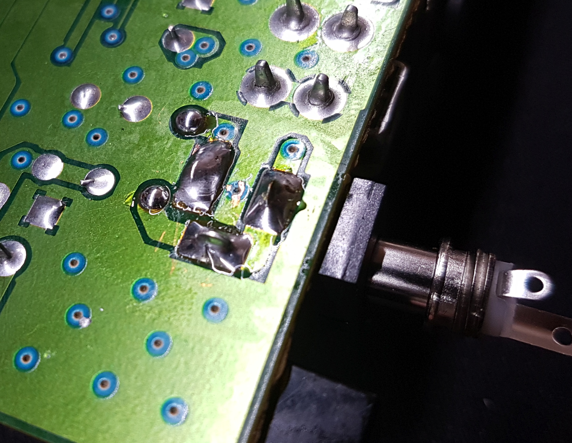
The whole pad was lifted and had to go. Mind the cold joints at the mounting bracked just to the right.Just a close upGlued down a piece of copper tape with super glue.Slit the tape in the middle and stuffed it down the holeStuck it down by soldering both sides to the remaining copper trace of the pcb.After letting the glued set for a few minutes I popped in a new socket. Luckily the footprint of these are common.
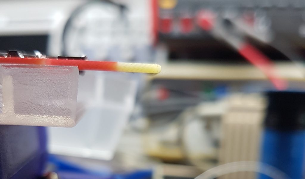
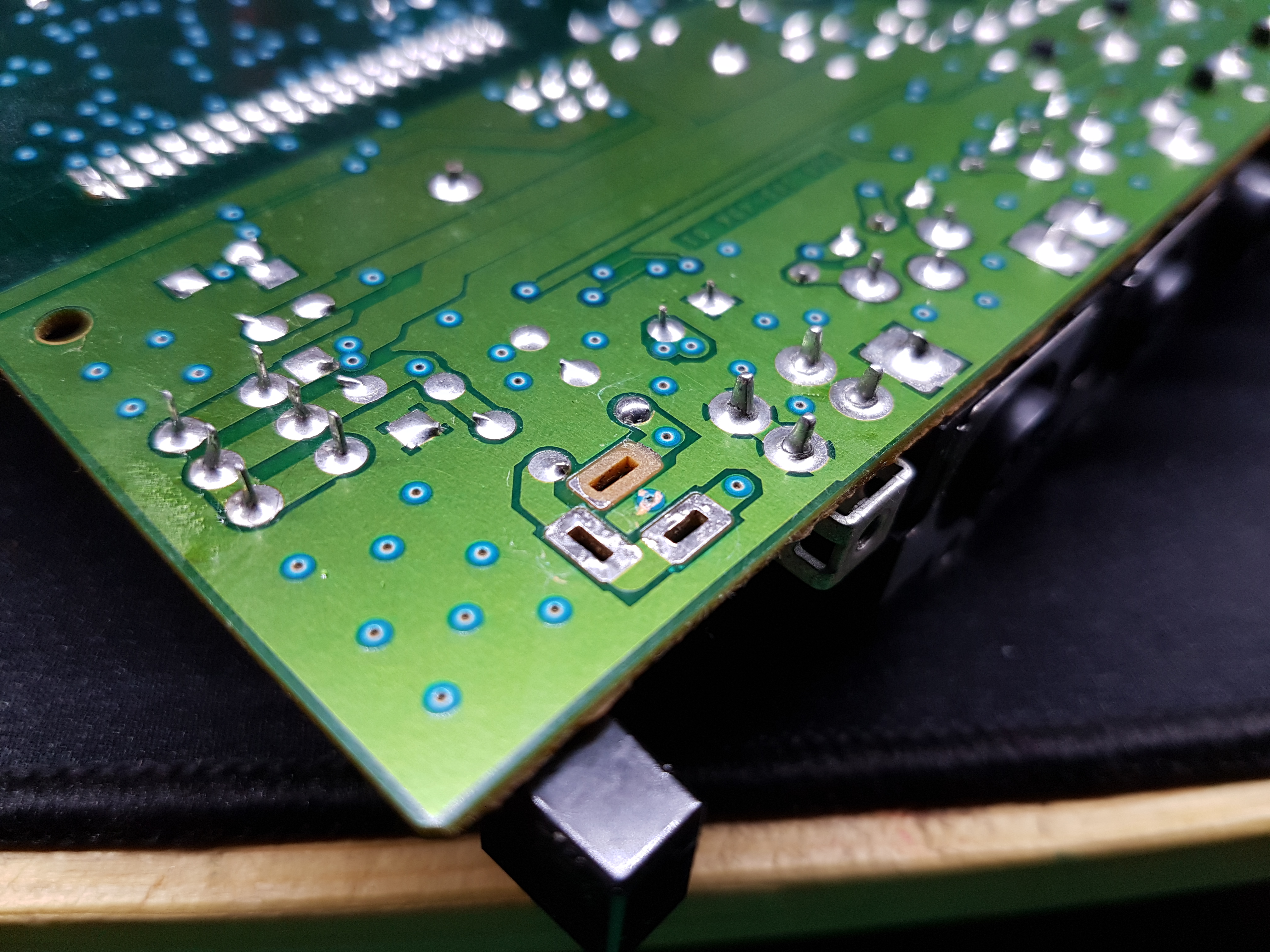
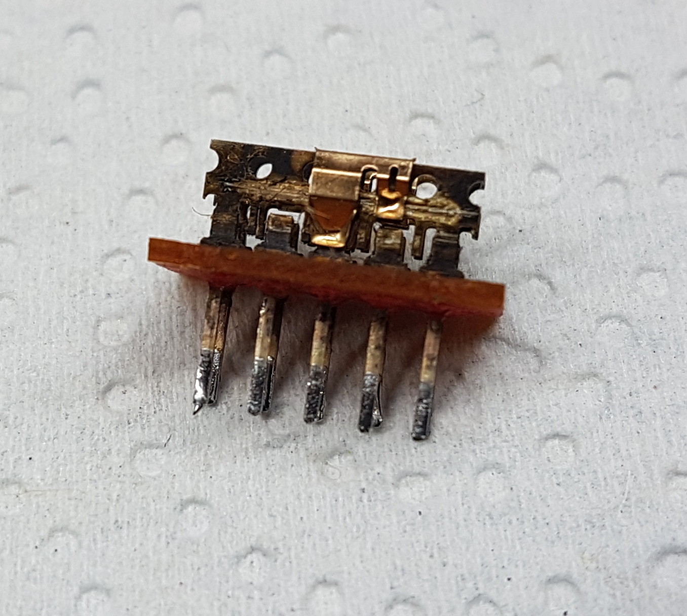
Next up was the input selector switch. First of all I desoldered it and checked how it was wired inside to find a replacement.
Tell me your secrets!
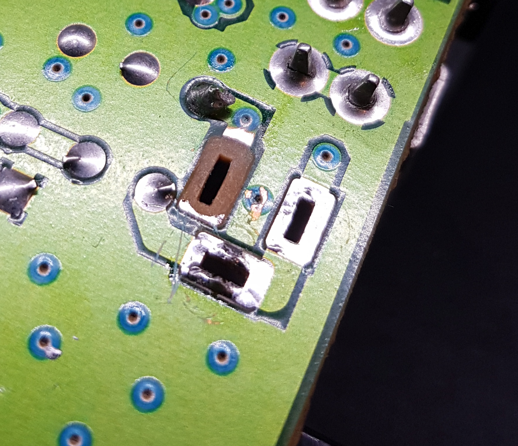
So after prying the outer shell it revealed all of its oxidised beauty.
EEK!
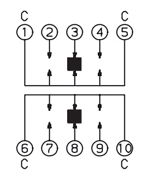
After giving it a scrub with brake cleaner I got this diagram:
Easy enough!
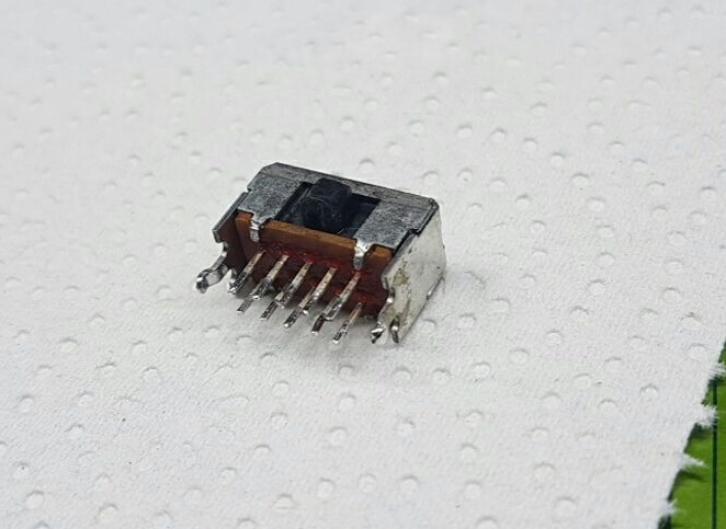
Well, its almost impossible to find a switch that is wired just like this. I’ve searched all the big retailers to no avail. Bummer. So I popped some other switches open to put in just the plastic piece in the broken switch. And hey, that worked just fine!
Living with the parts of his fallen brothers
So I soldered the “new” switch back in and tried to power it up. Bingo! It works just fine. So I focused at the shell again.
Next up I tackled the tape residue with goo gone. Just smeared it everywhere and put the case aside. Next up to see what the metal bottom was doing.
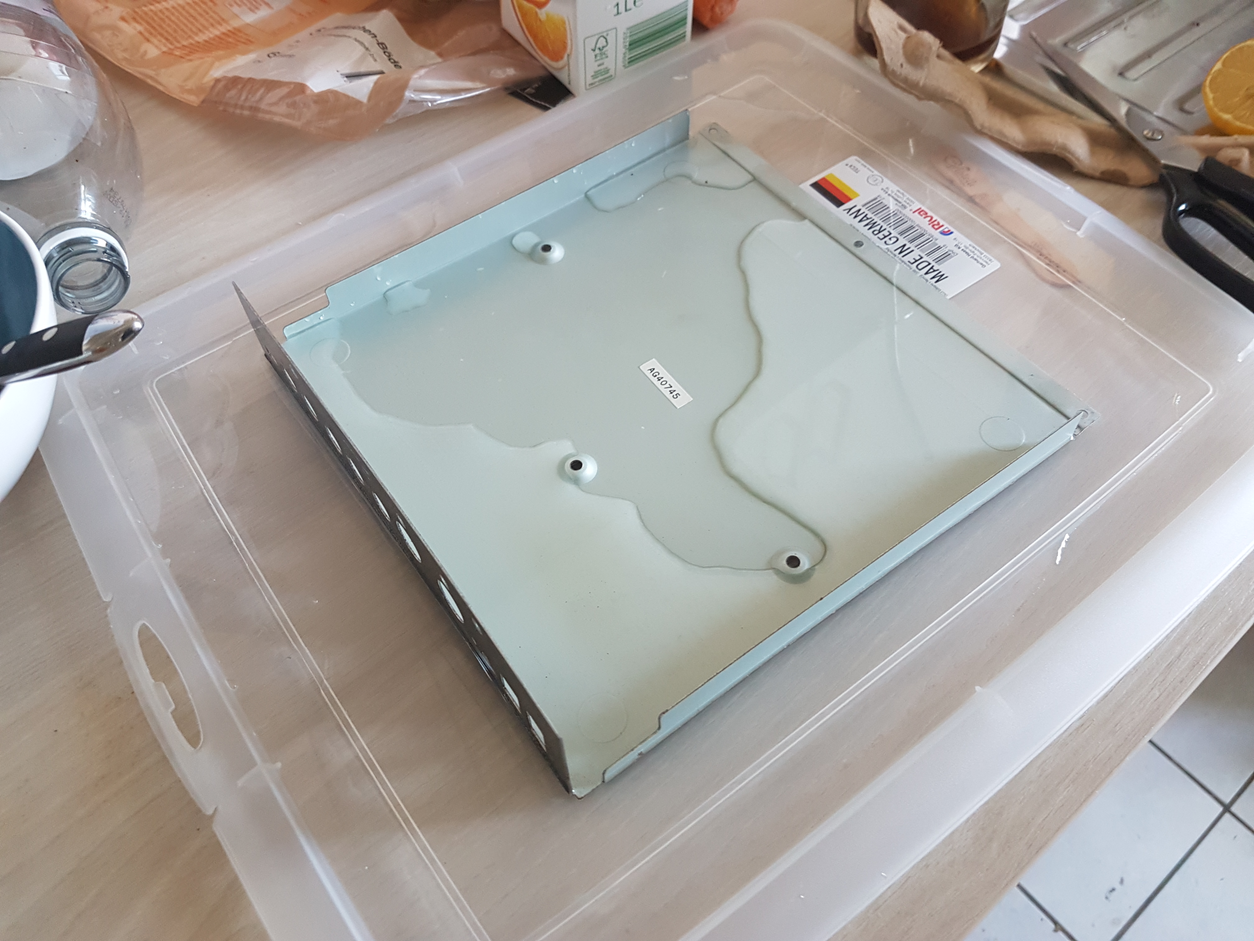
Smells like vinegar
Awesome! The vinegar ate all the rust away. Just wiped it in soapy water and scrubbed the plastic shell again. After that I just put everything together again.
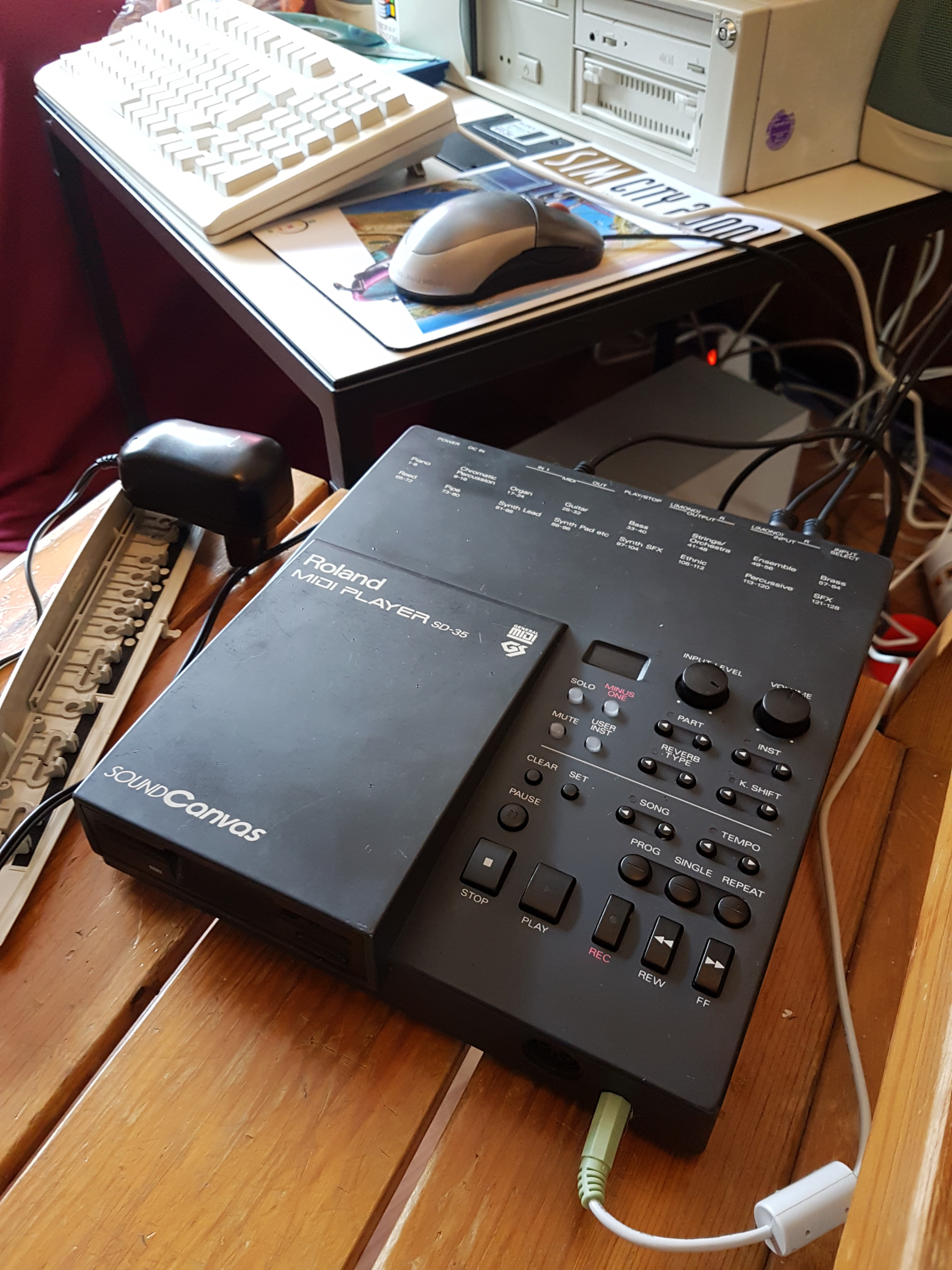
Play it again, Roland…
That wraps it up! The sound canvas works nicely with my old PC. Oh, the disk drives works, too. Took a video of it for your hearing pleasure 🙂