This tutorial tells you how to make a (Mr.) Gimmick!-Repro for the Nintendo Famicom.
If you want to play it on a NES system please be aware you need to modify the NES and the 60/72-Pin-Adapter in order to hear the additional sound channels.
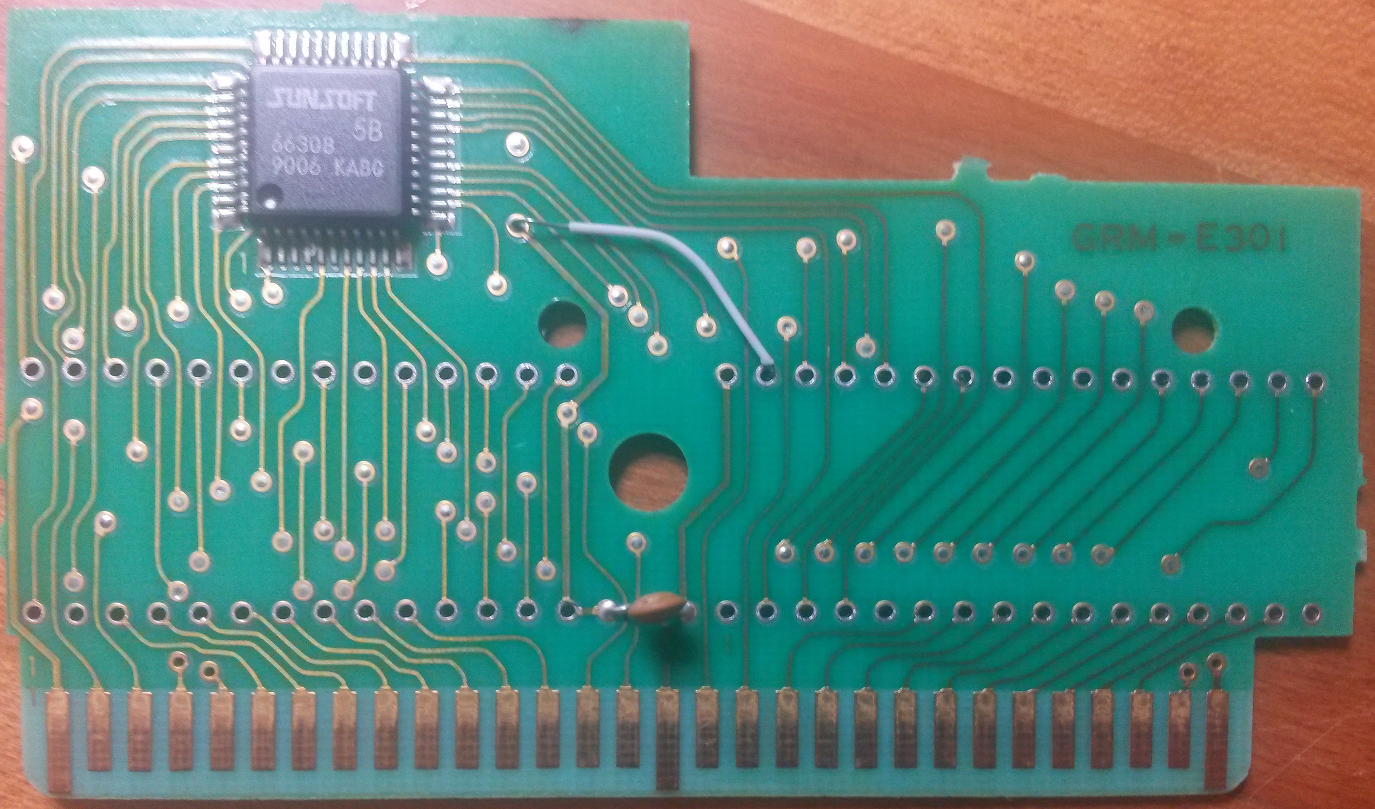
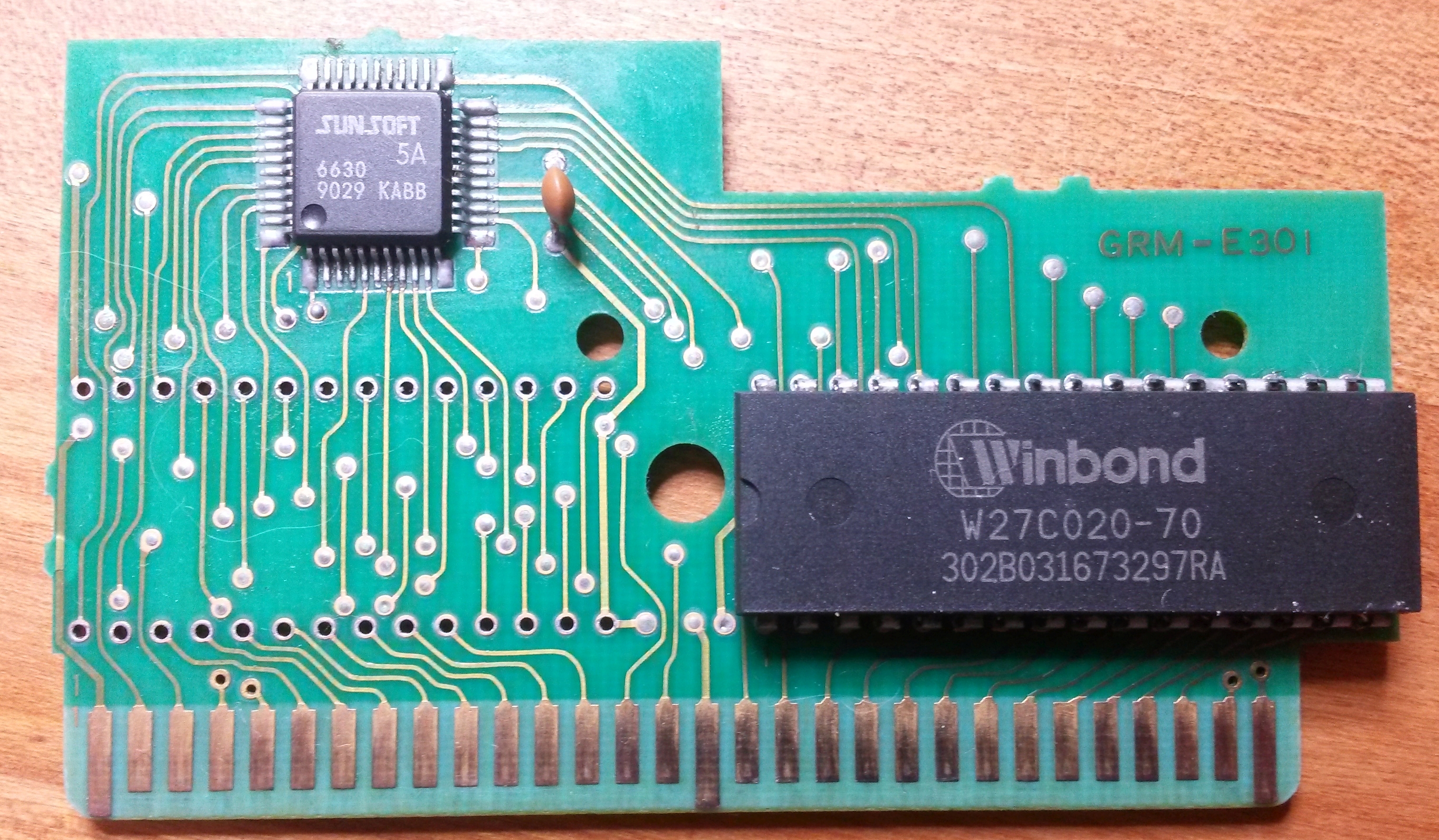
Gimmick! uses a special sound chip for it's awesome music. The chip is called "SUNSOFT 5B", or 5B for short. Gimmick! was officially the only game to use that chip.
Luckily though some other games used the chip (or similar chips) as well, so we can use them as a donor cartridge for this tutoral!
I'll use the japanese version of Gimmick (Gimmick! (Japan).nes, CRC:15F688B6), since I like it the most. Hacks of the game and the beta version should work with this tutorial as well.
MANY MANY THANKS to: the guys over at famicomworld.com & xIceMan in particular! Without his help this tutorial wouldn't have been possible.
Special thanks to Commodore64 for spending love and kisses whenever I felt sad.
Update: If you want to have a PCB made for easy repro-ing, here you go:
You could do it with a hex editor by that's unnecessary difficult.
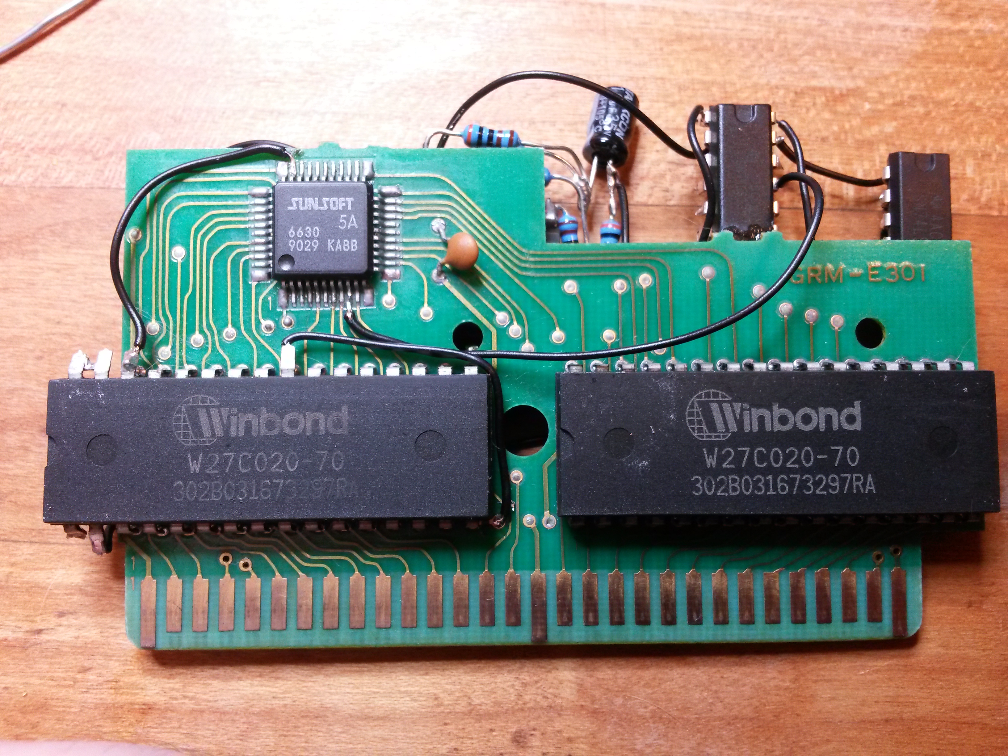
When you got your splitted rom burn the CHR and the PRG-parts to your EPROMs.
I recommend using EEPROMs since thay last quite long. UV-erasable EPROMs are fine too, but they won't last as long as EEPROMs.
If you can't do this step by yourself just contact me (jensma@jensma.de), the guys over at nesdev.com or consider buying a preprogrammed (E)EPROM from a shop.
Consider buying two 27C020, they work fine and are probably cheaper to get then two different EEPROMs. Most seller offer special deals when you buy them in a lot.
Open the shell and identify the sound chip
If you wonder how to open Famicom cartridged just have a look at this video by arfink on youtube:
If you don't have a clamp at hand you might want to try the way harder way by poking screwdrivers into the shell. It'll most probably damage the shell though. Just have a look at google for this method (can't recommend it).
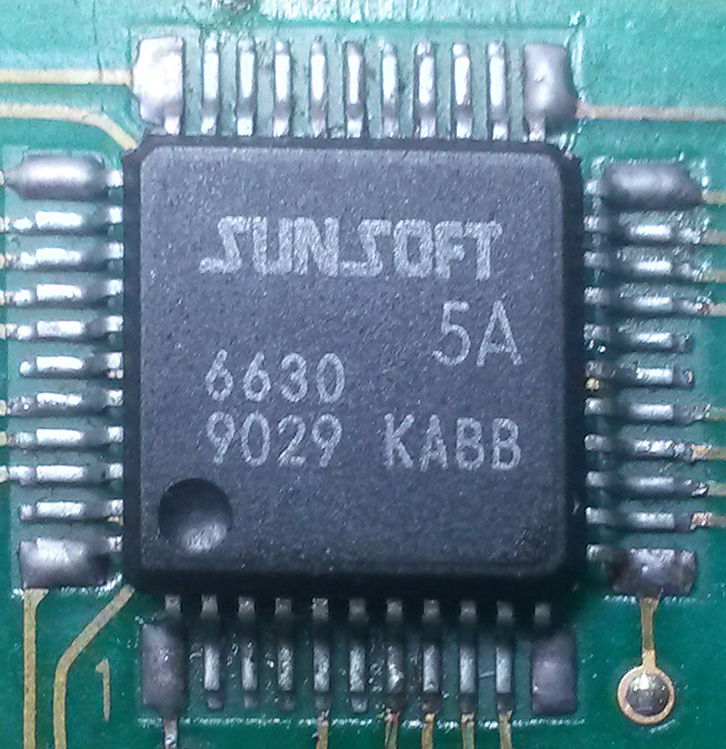
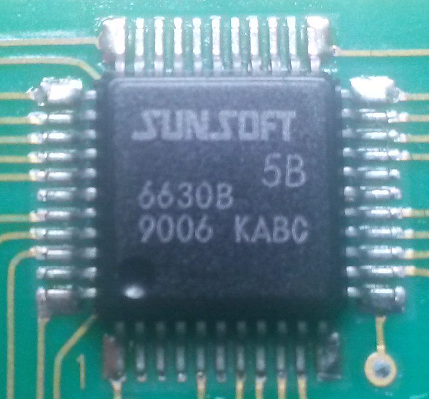
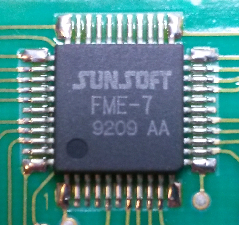
After you've managed to pop up the game search for the square ic and read the printing on it.
It's pure luck which sound IC you get. You get either a 5A, a 5B or a FME-7.
5A
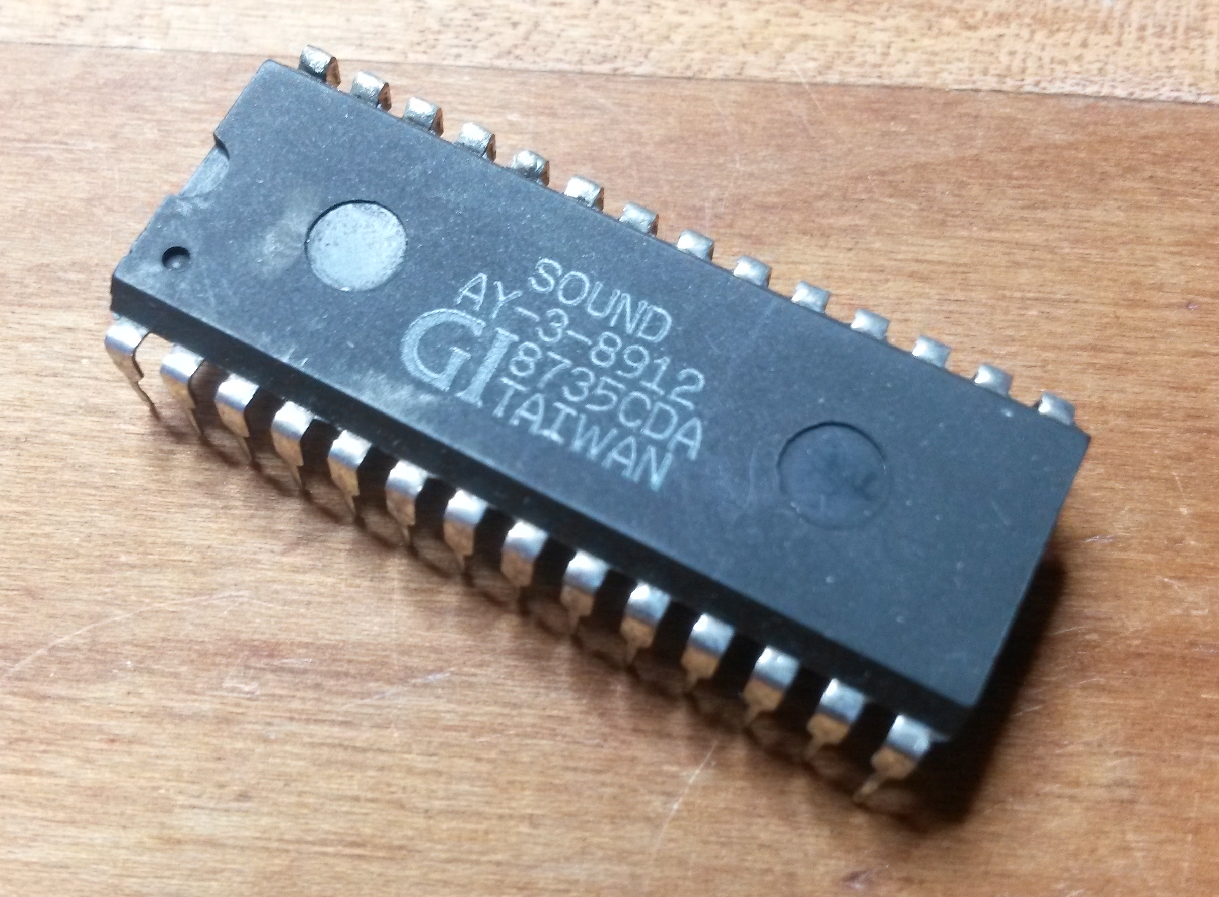
5B
FME-7
I found the sound ic, what now?
These games come either with a 5B (less modifications needed ) or an 5A / FME-7 (more modificatiosn needed).
Just refer to the tutorial below, whenever you have to do modification depending on your sound ic it'll be highlighted!
Step 1: Desoldering (5A and FME-7, 5B)
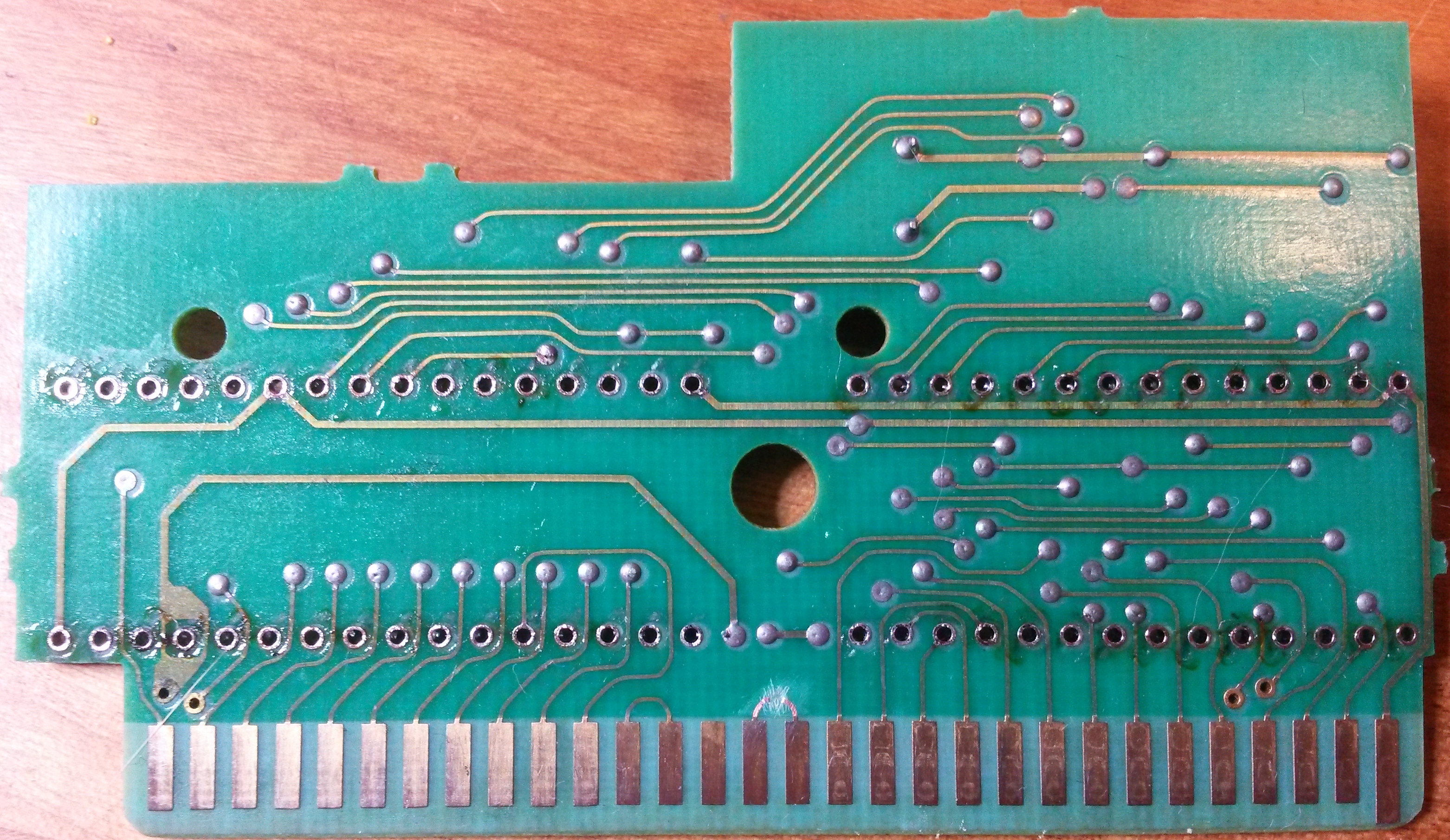
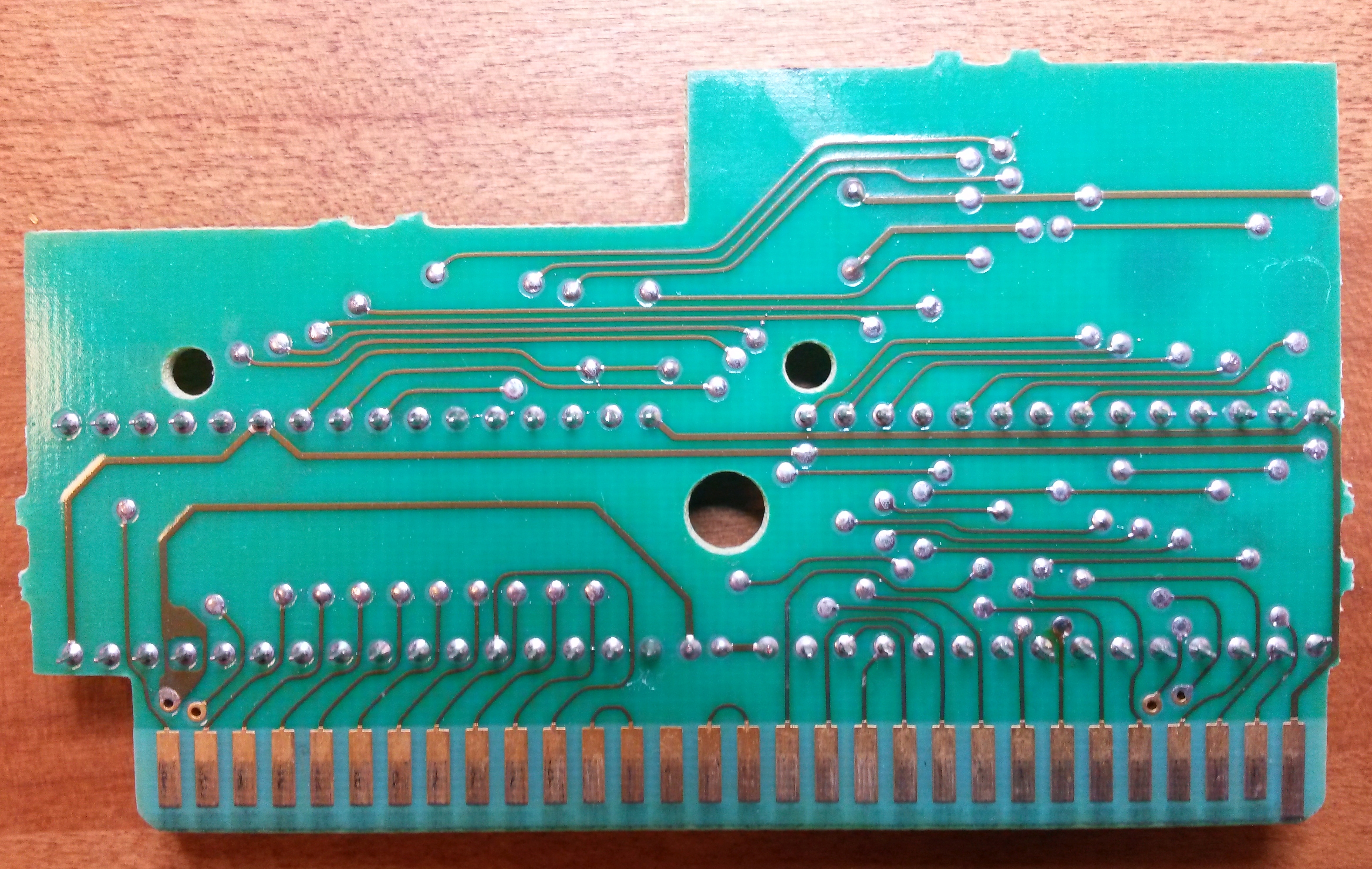
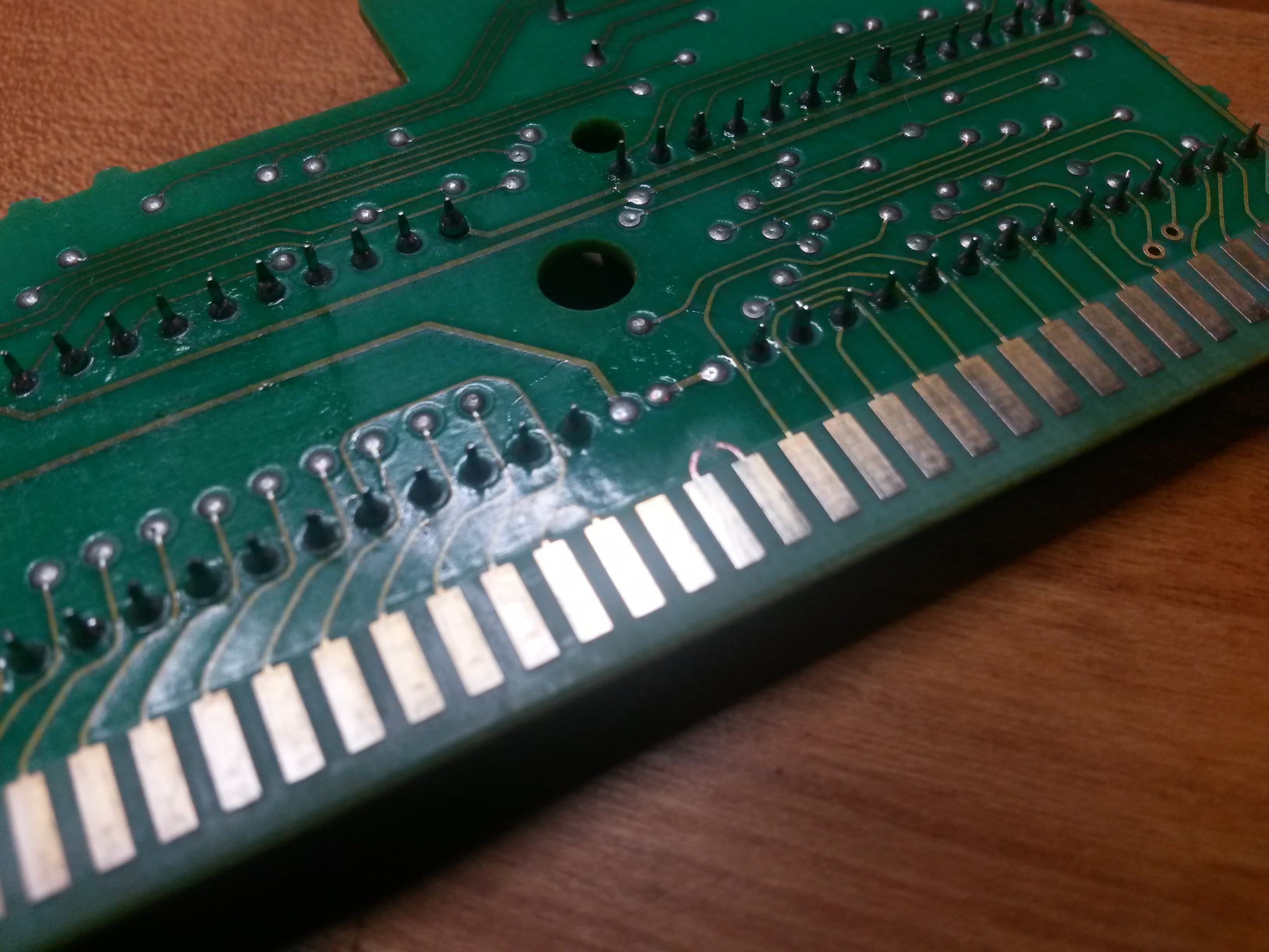
In the first step you'll have to desolder and remove the original mask roms. Just flip the pcb over and desolder every leg of the mask roms.
A desoldering station comes in handy, but solder wick will do the job too. If you don't know how to desolder electronics, head over to youtube.
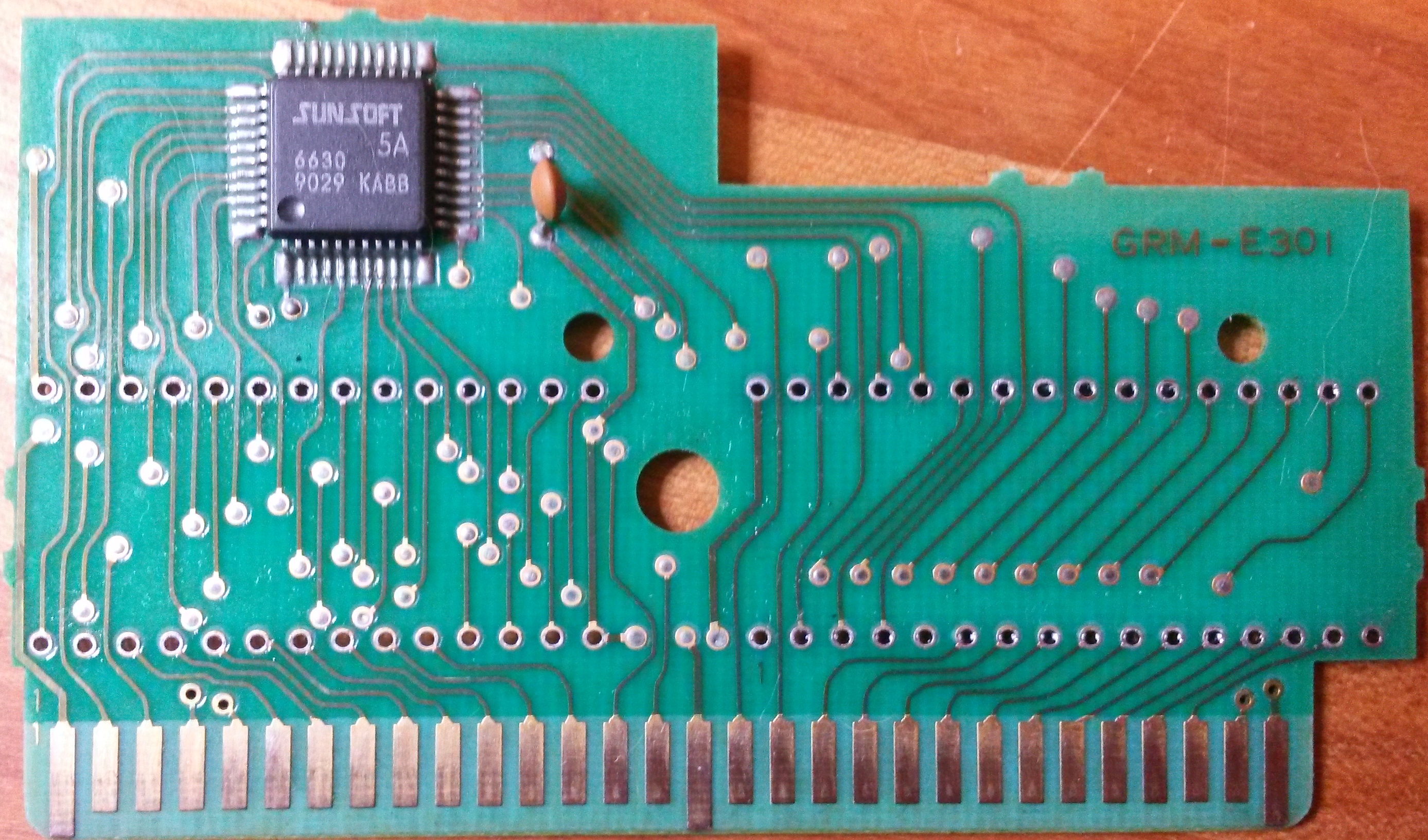
Have a look at some (partly) desoldered pcbs:
5A
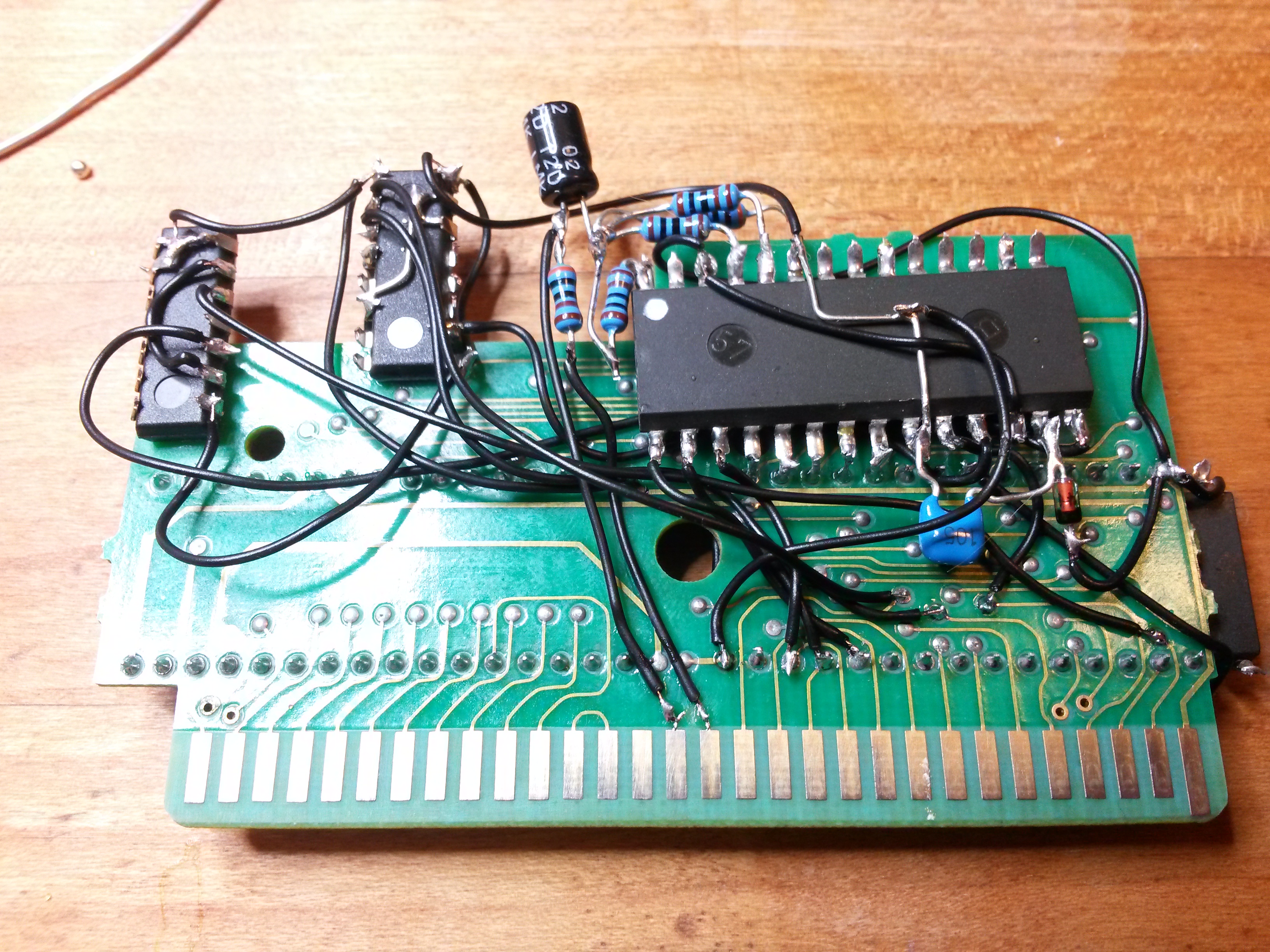
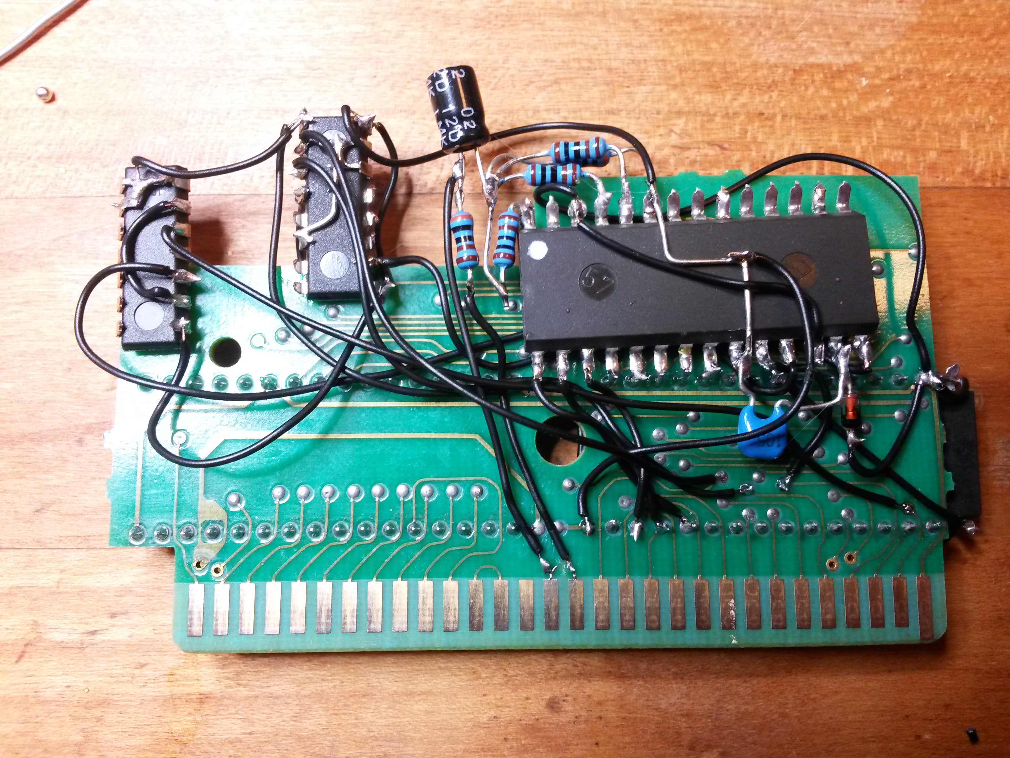
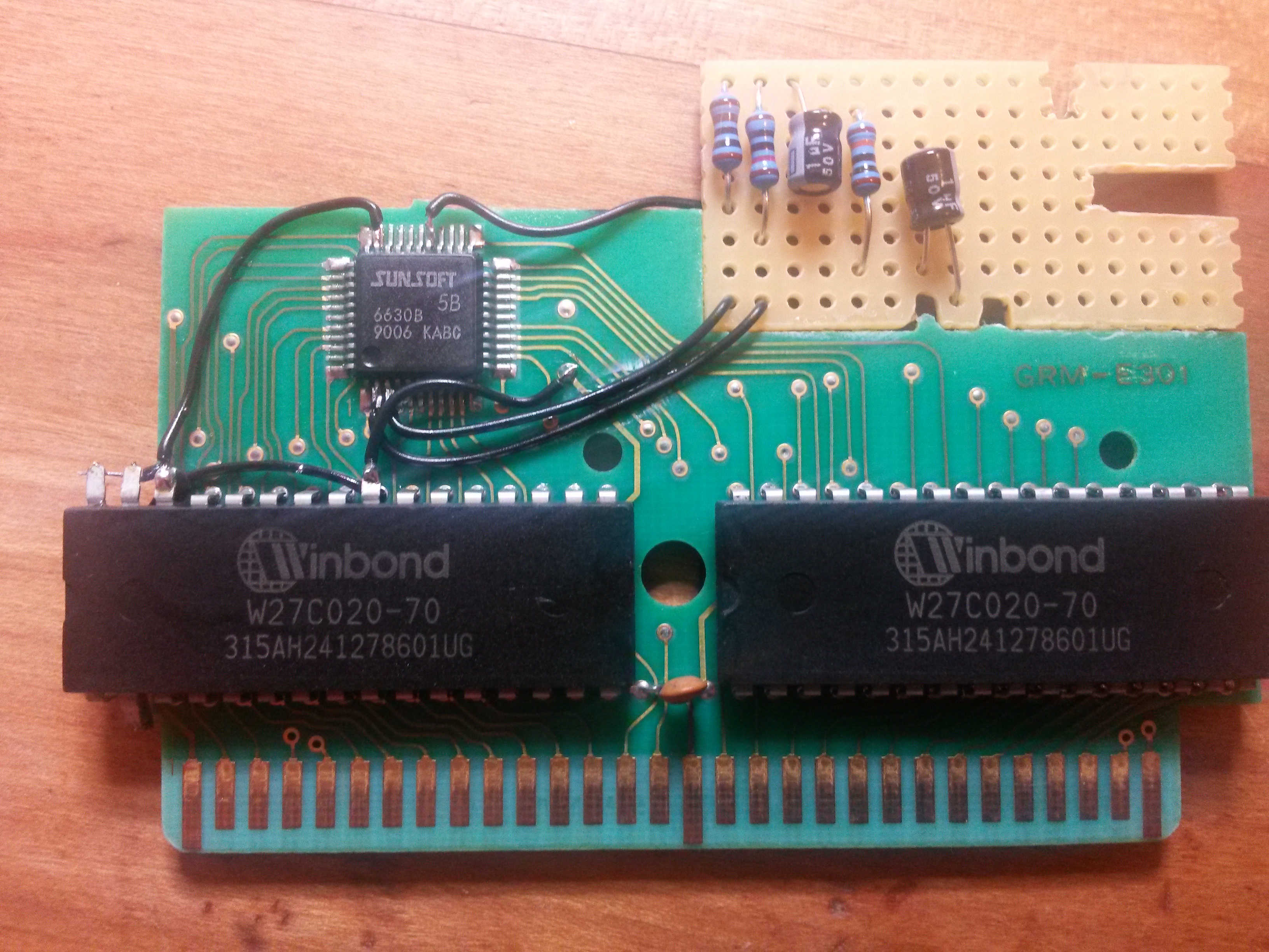
5B
FME-7
If you got a botched wire like on the 5B-board and the FME-7-board - just remove it.
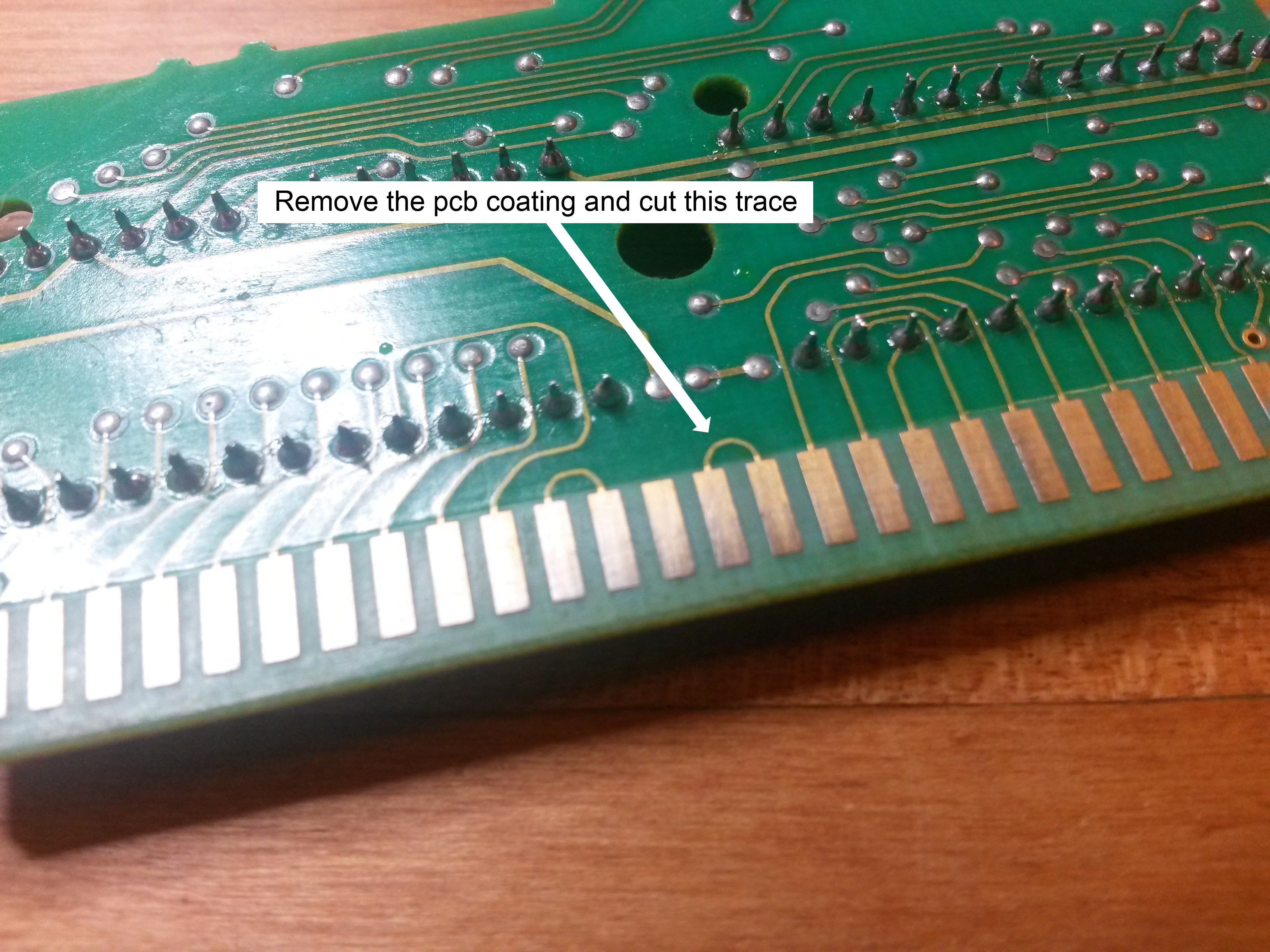
Step 2: Free the sound pins (5A and FME-7, 5B)
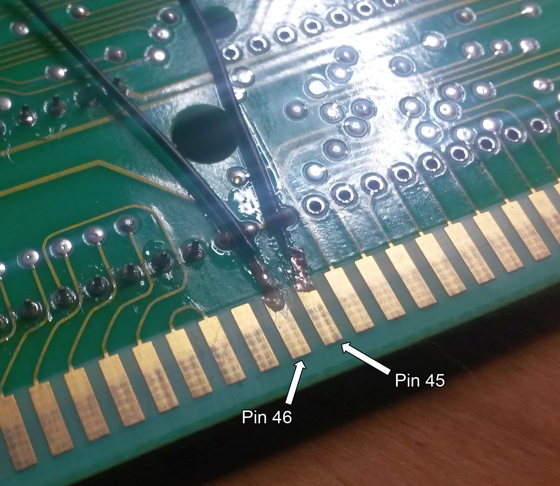
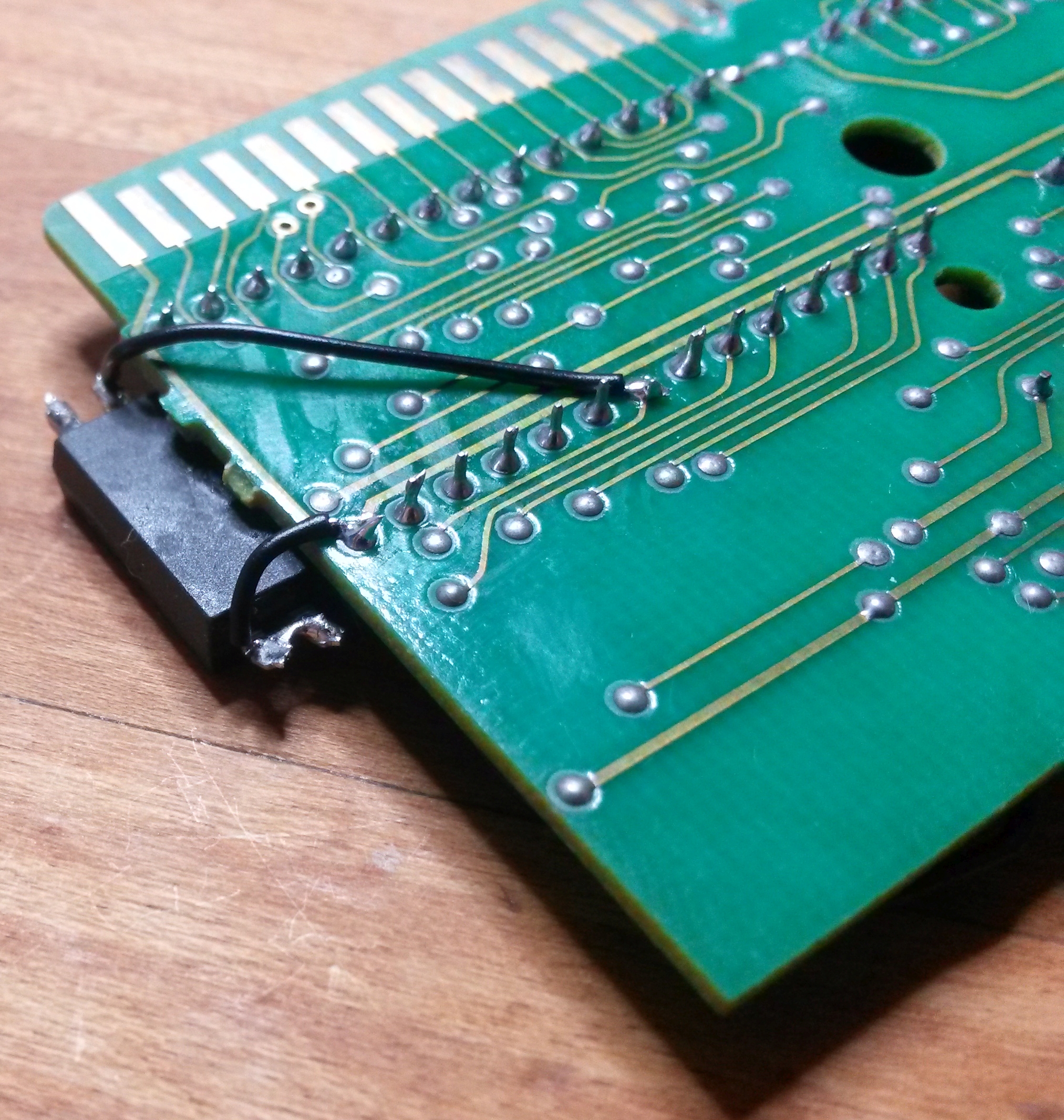
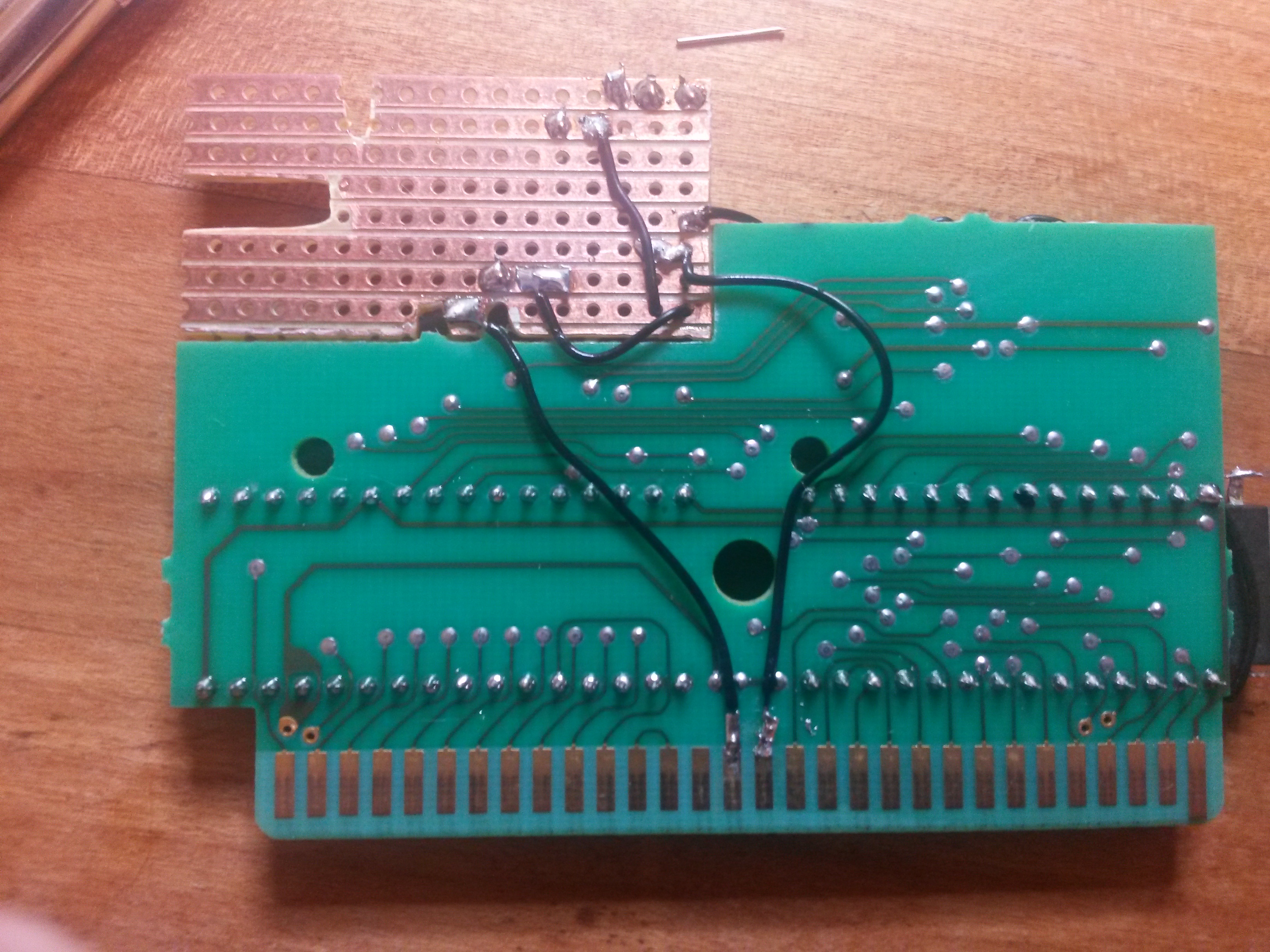
Remove the coating of the trace between the 45th and 46th pin of the cartridge's pcb and cut it.
I used a fiber glass pen to scrape the coating away. Make sure not to cut the trace away completely since you have to solder wires to them.
The trace you need to cut
Coating removed, note the shiny copper traces
Cut traces
Solder wires to the exposed copper traces
When in doubt of a physically strong connection glue the wires to the pcb in addition to your solder job.
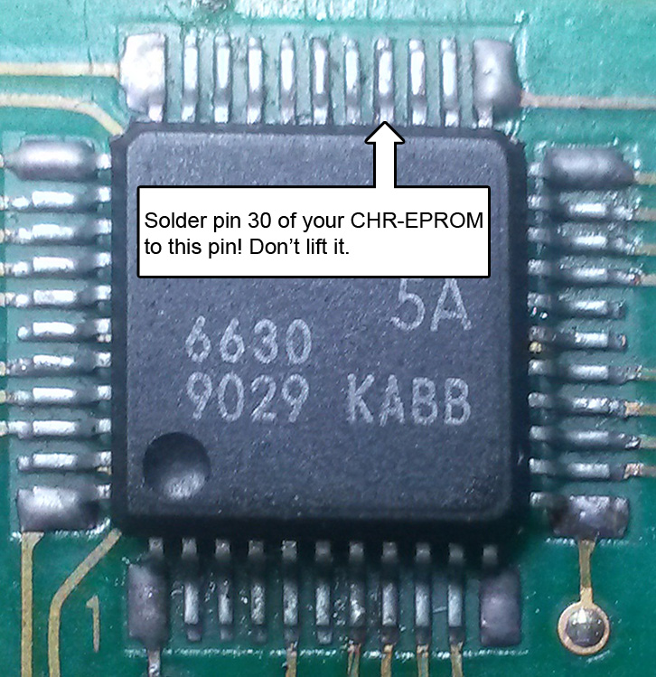
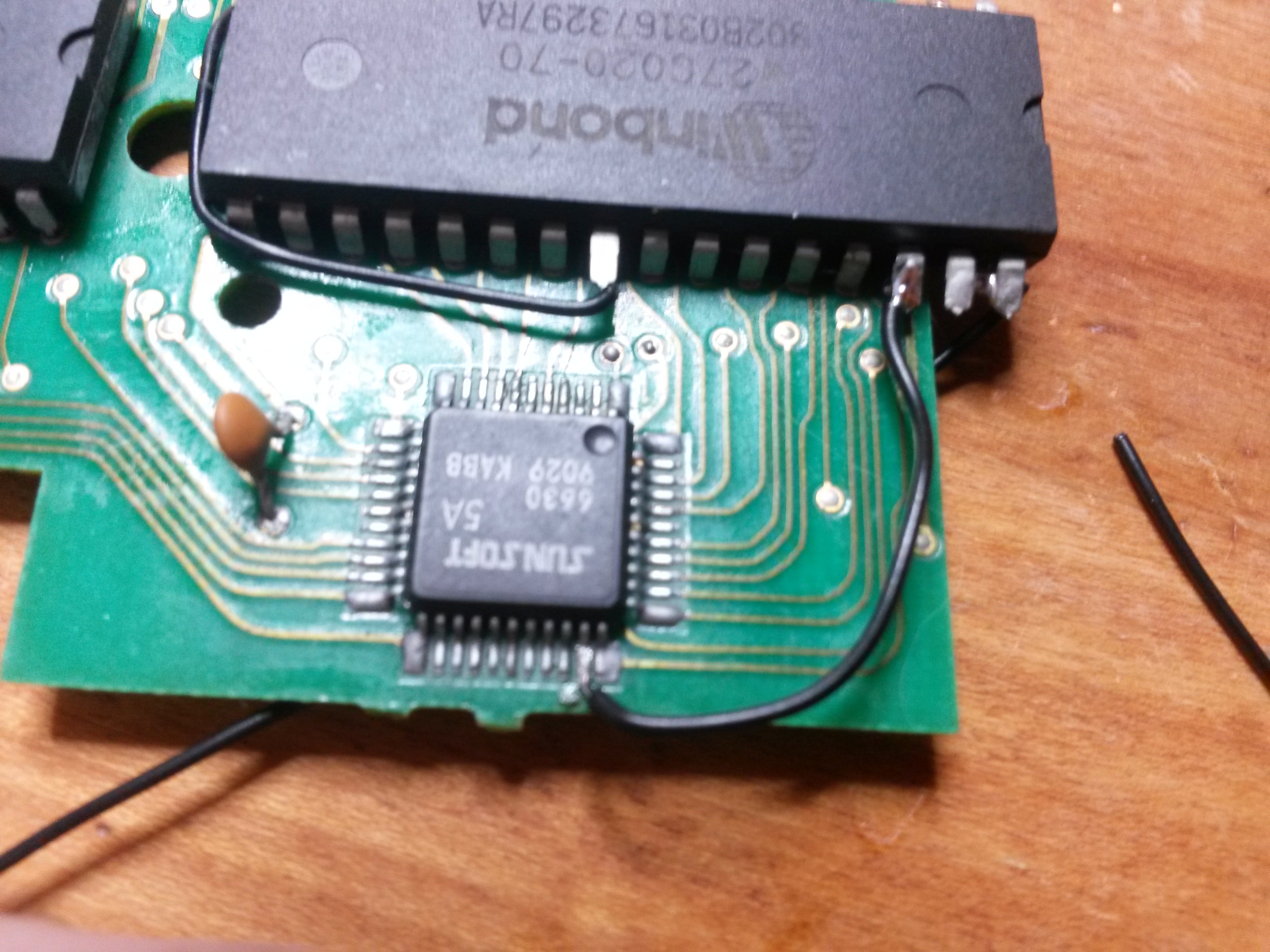
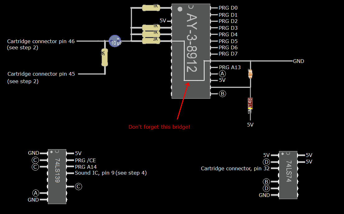
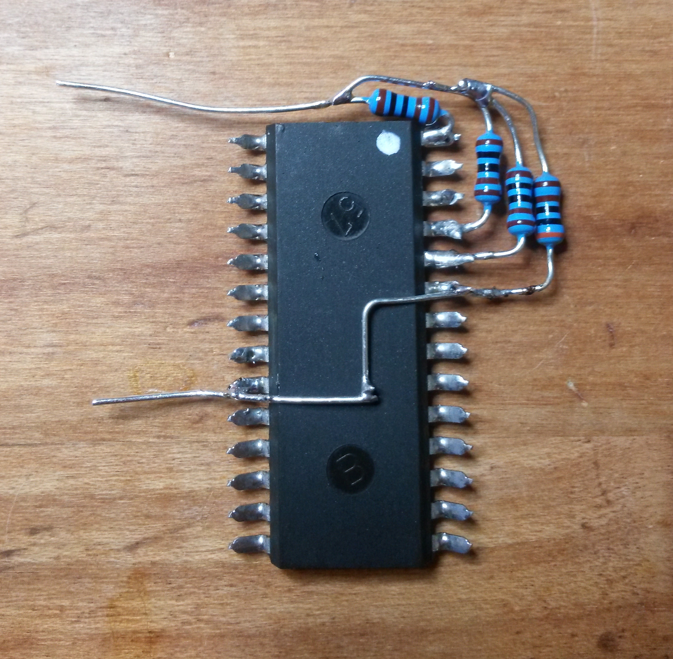
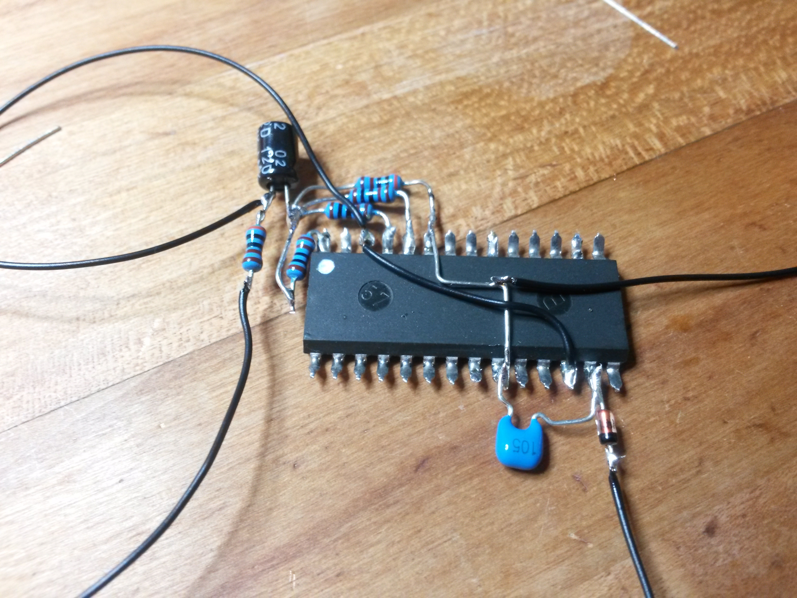
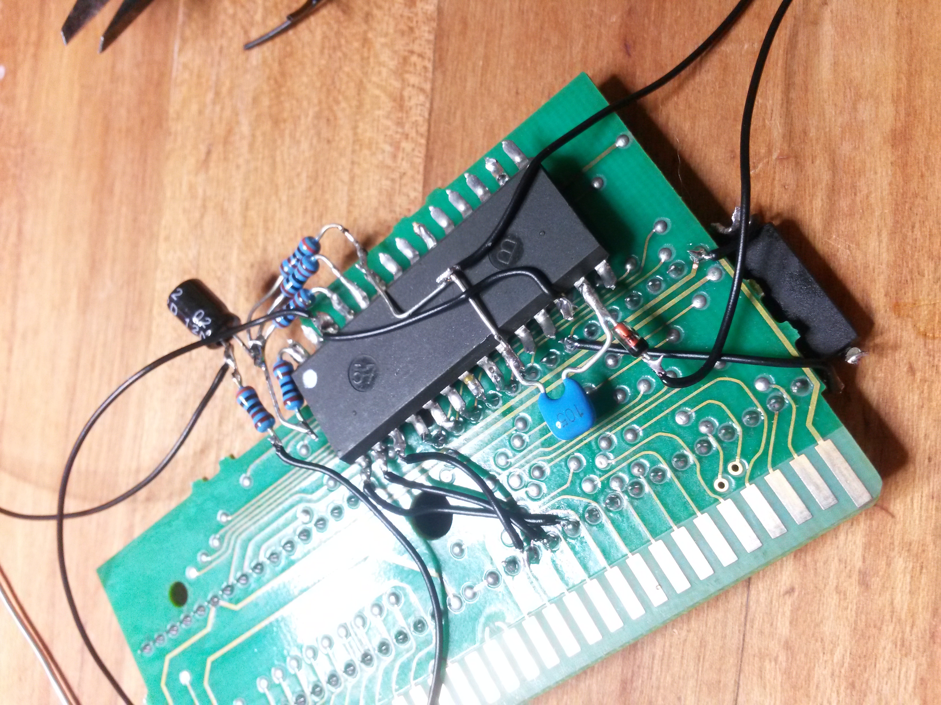
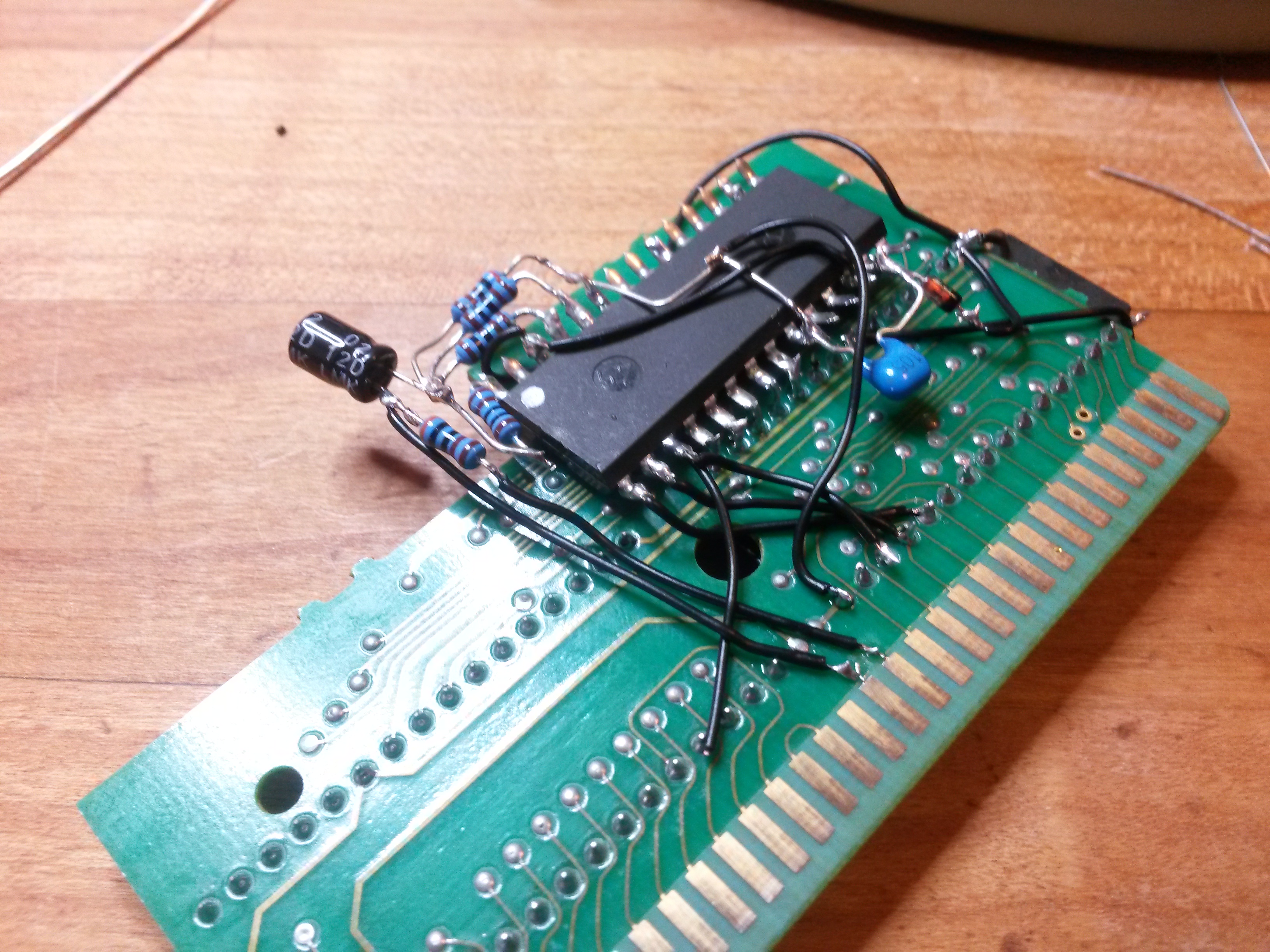
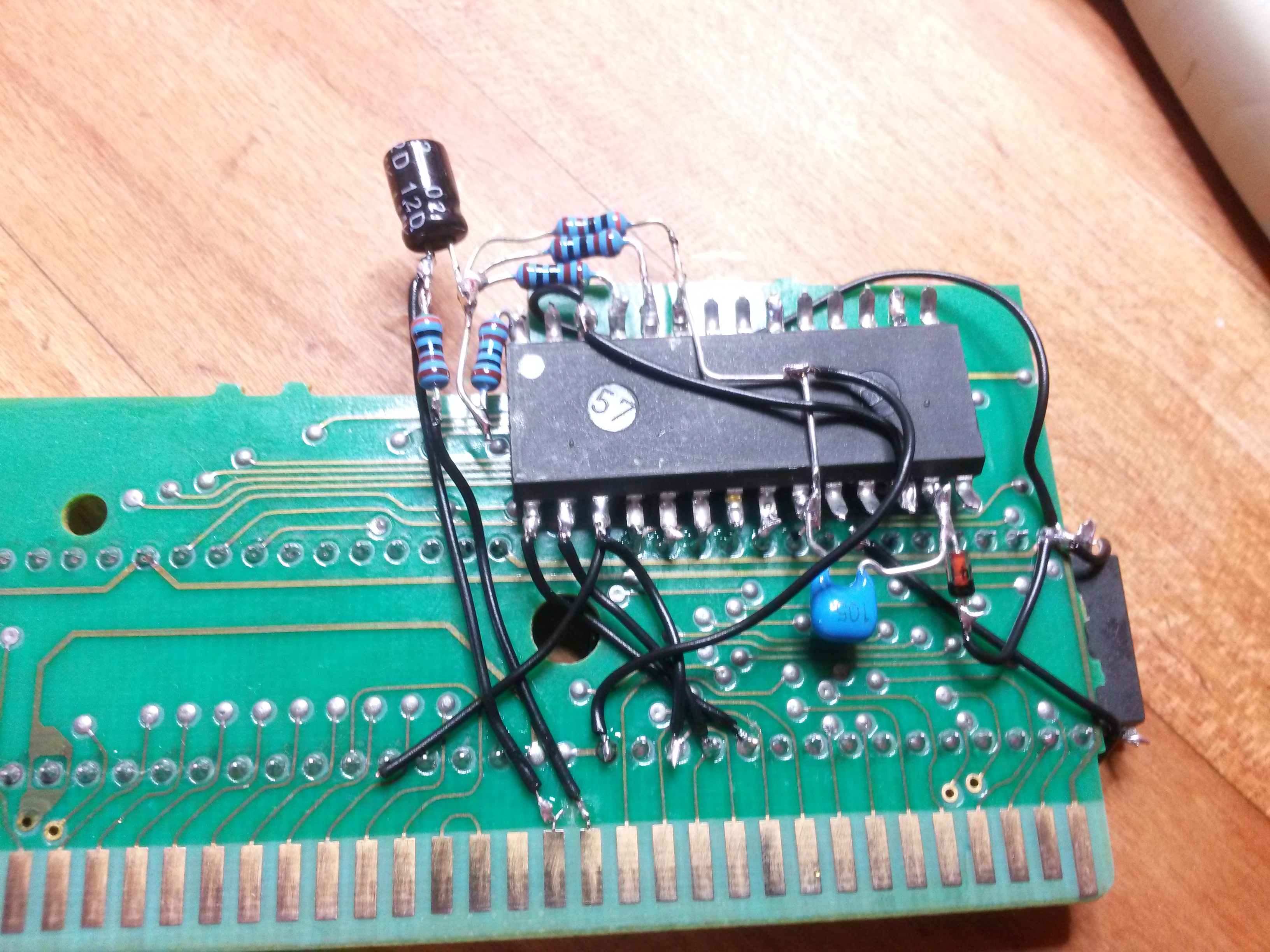
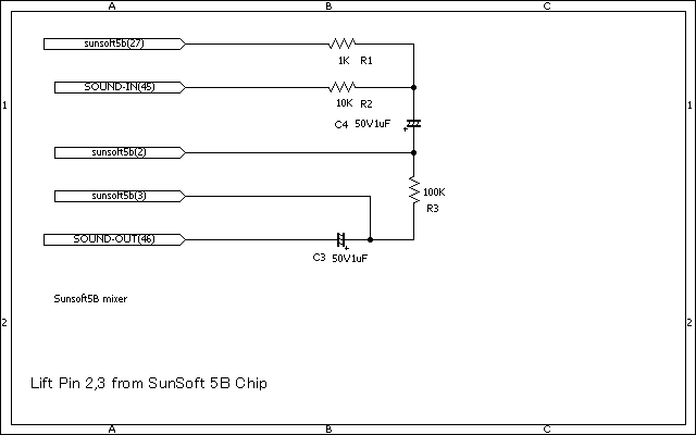
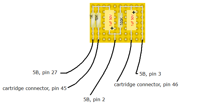
Step 3: Prepare your 5B (5B only!)
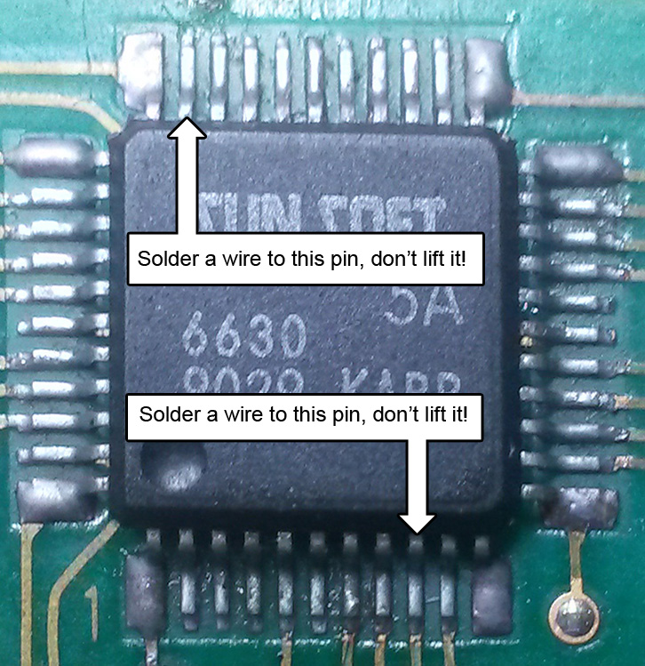
In this step you have to solder some wires to your 5B.
Lift these pins and solder wires to it: 2, 3, 27
Then solder a wire to pin 32, but don't lift it.
Have a look at this image for your reference:
Double check if the pins are disconnected from the pcb's footprint!